
Open Circuit Structure and De-embedding Method of Spiral Inductor

A spiral inductance, de-embedding technology, applied in the direction of transformer/inductor coil/winding/connection, preventing/reducing unwanted electrical/magnetic effects, etc., can solve the problem of incomplete de-embedding, large self-resonant frequency deviation, Problems such as low self-resonant frequency to achieve the effect of improving accuracy

Active Publication Date: 2020-06-12
SHANGHAI HUALI INTEGRATED CIRCUIT CORP
View PDF4 Cites 0 Cited by
  • Summary
  • Abstract
  • Description
  • Claims
  • Application Information

AI Technical Summary

Problems solved by technology

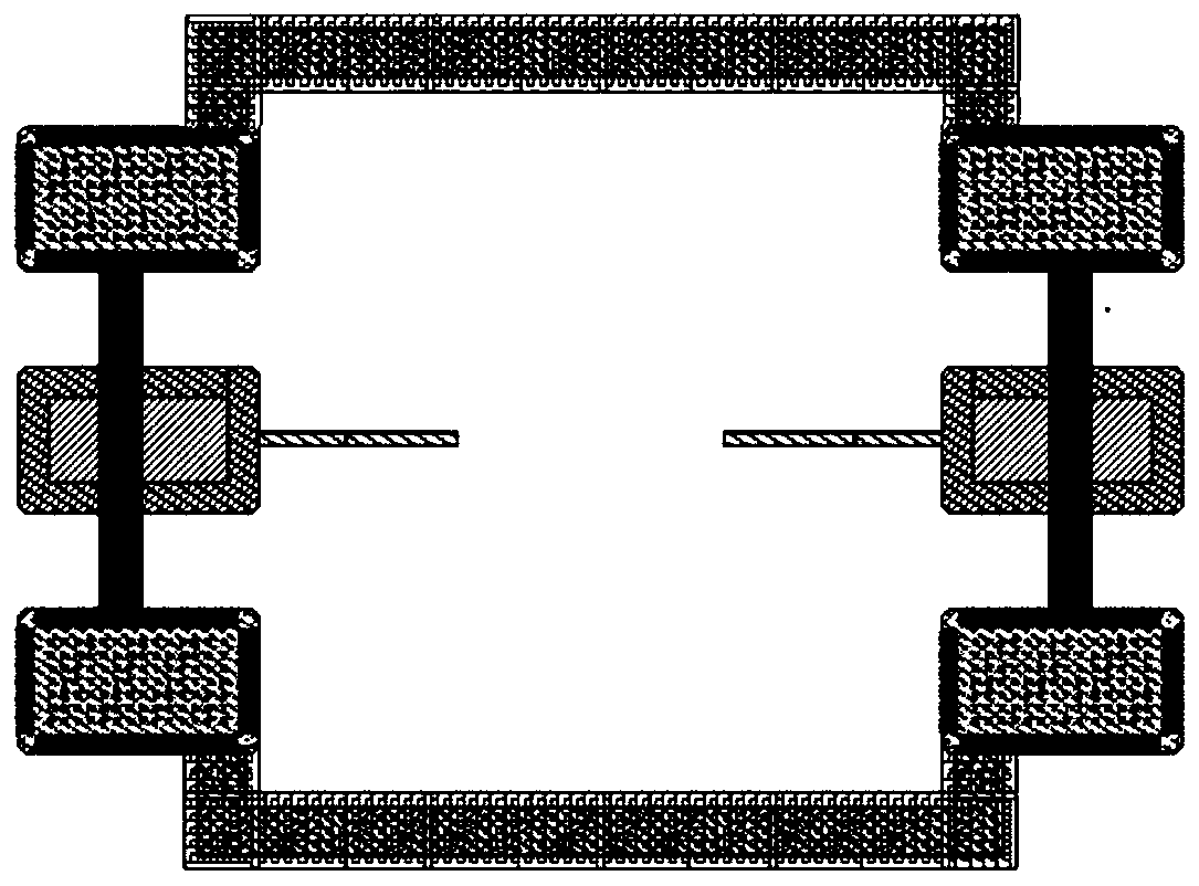
[0003] However, at present, the inductance characteristics are usually obtained by de-embedding an open-circuit structure of a spiral inductor. However, in the existing open-circuit structure for de-embedding the spiral inductor, the parasitic capacitance of the spiral part to the ground ring is not deducted, resulting in incomplete de-embedding. The accurate inductance characteristics are not obtained, so the self-resonant frequency is low, and it often occurs that when the electromagnetic field simulation software is used to simulate the inductance, the self-resonant frequency deviation is large
Especially when only pure inductance is simulated in the electromagnetic field simulation software, that is, there is no grounding ring

Method used


Image

  • Open Circuit Structure and De-embedding Method of Spiral Inductor
  • Open Circuit Structure and De-embedding Method of Spiral Inductor
  • Open Circuit Structure and De-embedding Method of Spiral Inductor

Examples


Embodiment Construction

[0019] The technical solutions in the present invention will be clearly and completely described below in conjunction with the accompanying drawings. Apparently, the described embodiments are part of the embodiments of the present invention, not all of them. Based on the embodiments of the present invention, all other embodiments obtained by persons of ordinary skill in the art without making creative efforts belong to the protection scope of the present invention.

[0020] see figure 1 , figure 1 A schematic diagram of a spiral inductor. like figure 1 As shown, the spiral inductor includes an inductor spiral winding part 110 on the substrate, a first inductor lead terminal 121, a second inductor lead terminal 122, and a pin 123 connected to the first inductor lead terminal 121 and a second inductor lead terminal. Pin 124 of terminal 122 . The substrate also includes a grounding ring, the grounding ring includes a first winding part 131, a first pin 133 and a second pin 13...


PUM


Abstract

The invention relating to the radio frequency device structure relates to a de-embedding open-circuit structure of a spiral inductor. The de-embedding open-circuit structure comprises a spiral inductor, a first ground ring, and a second ground ring. The spiral inductor includes an inductor spiral winding portion, a first inductor leading terminal, a second inductor leading terminal, a pin connected with the first inductor leading terminal and a pin connected with the second inductor leading terminal; and the inductor spiral winding portion is broken in the middle. The first ground ring encircles the spiral inductor; and the second ground ring encircles the first ground ring. Therefore, the accurate spiral inductance characteristics are obtained to improve the accuracy of circuit simulation.

Description

technical field [0001] The invention relates to a radio frequency device structure, in particular to an open-circuit structure for de-embedding a spiral inductor and a de-embedding method thereof. Background technique [0002] In RF device structures, accurate spiral inductor characteristics are required to improve the accuracy of circuit simulations. [0003] However, at present, the inductance characteristics are often obtained by de-embedding an open-circuit structure of a spiral inductor. However, in the existing open-circuit structure for de-embedding the spiral inductor, the parasitic capacitance of the spiral part to the ground ring is not deducted, resulting in incomplete de-embedding. The accurate inductance characteristics are not obtained, so the self-resonant frequency is low, and it often occurs that when the electromagnetic field simulation software is used to simulate the inductor, the self-resonant frequency has a large deviation. Especially when only pure i...

Claims


Application Information

Patent Timeline
Patent Type & Authority Patents(China)
IPC IPC(8): H01F27/28H01F27/29H01F27/34
CPCH01F27/28H01F27/29H01F27/34
Inventor 何丹
Owner SHANGHAI HUALI INTEGRATED CIRCUIT CORP
Learn More