Ultrahigh current density electrolysis or electro-deposition groove

A current density and electrowinning cell technology, applied in the direction of cells, etc., can solve the problems of electrolytic cell leakage, damage to the anti-corrosion layer, damage to the box, etc., to achieve the effect of smooth production and ensure safety.

Active Publication Date: 2013-08-21
YANGGU XIANGGUANG COPPER +2
View PDF6 Cites 14 Cited by
  • Summary
  • Abstract
  • Description
  • Claims
  • Application Information

AI Technical Summary

Problems solved by technology

However, since the electrolyte inlet tank of the device is hung on the wall of the electrolytic cell, the cathode or anode is very easy to touch the liquid inlet tank in actual production and cause damage to the tank, and even damage the anti-corrosion of the inner wall of the electrolytic cell in severe cases. Leakage of the electrolytic cell caused by the layer, which is not conducive to smooth production and safe operation

Method used


Image

  • Ultrahigh current density electrolysis or electro-deposition groove
  • Ultrahigh current density electrolysis or electro-deposition groove
  • Ultrahigh current density electrolysis or electro-deposition groove

Examples


Embodiment 1

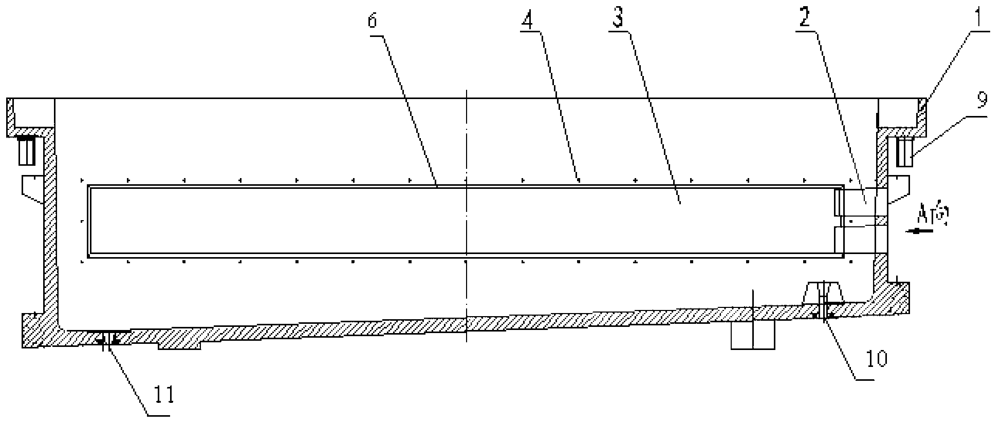
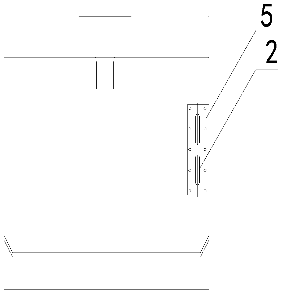
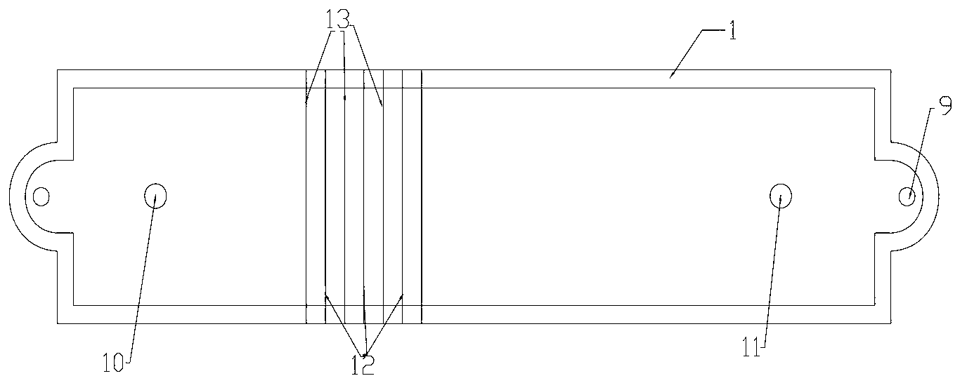
[0064] In the electrolytic cell, 54 rough copper anode plates 13 and 53 pure copper cathode plates 12 are placed at intervals, the mixed solution of sulfuric acid and copper sulfate is used as the electrolyte, and the external liquid supply system is connected to the liquid supply device through the flange 5 to supply After the electrolyte is energized, the supplied electrolyte enters the closed cavity 3 of the liquid supply device through the liquid inlet 2, and is evenly distributed along it, and passes through the electrolyte spraying device 8 on the panel 6 along the parallel and close to The direction of the cathode plate is ejected, and then the ejected electrolyte moves to both ends of the cell through the cavity between the electrode plate and the side wall of the cell, and the cavity between the electrode plate and the bottom of the cell, and finally flows from the two sides of the cell. The overflow port 9 at the end returns to the electrolyte circulation system.

[...


PUM


Abstract

The invention provides an ultrahigh current density electrolysis or electro-deposition groove comprising a groove body, wherein the groove body is provided with a liquid inlet; a flange is arranged at the outer part of the liquid inlet; a panel is arranged on the inner side wall of the groove body; a closed cavity is formed by the panel and the inner side wall of the groove body; the closed cavity is communicated with the liquid inlet in the groove body; the panel is provided with an electrolyte spraying device and a polar plate limiting device; an anode plate and a cathode plate are placed in the groove body; and a liquid discharging device is arranged on the groove body. According to the ultrahigh current density electrolysis or electro-deposition groove disclosed by the invention, a liquid supplying device is formed by the panel, the inner side wall of the groove body and the closed cavity formed by the panel and the inner side wall of the groove body. The liquid supplying device disclosed by the invention is embedded into the inner side wall of the groove body and a liquid supplying manner that the bottom of the e liquid supplying device is parallel to polar plates is utilized so as to guarantee the electrolyte circulation requirements needed by electrolysis or electro-deposition production under the ultrahigh current density; and meanwhile, the polar plates are not contacted with the liquid supplying device which is embedded into the inner side wall of the groove body, so as to guarantee the safety of the liquid supplying device and the production is smoothly and safely operated.

Description

technical field [0001] The invention relates to the technical field of electrolysis or electrowinning of non-ferrous metals, in particular to an ultra-high current density electrolysis or electrowinning cell. Background technique [0002] Electrolytic refining is the main means of metal refining in the process of non-ferrous metal smelting, and it is also a final link of non-ferrous metal smelting. The advanced technology and equipment directly affect the quality of metals and the level of production capacity. Among non-ferrous metals, the electrolysis or electrowinning process of copper, lead, zinc and nickel is based on the principle of electrochemistry. The cathode and anode are placed in a tank containing a solution containing metal ions, and an electrochemical reaction occurs on the electrodes after electrification. , the metal on the cathode is continuously precipitated and deposited. Since the electrode potentials of various metal ions in the solution determine the o...

Claims


Application Information

Patent Timeline
IPC IPC(8): C25C7/00
CPCC25C7/00
Inventor 周松林林建平A.菲尔兹维泽王亚民柳彦宁万涛潘霞杨家庭王志普
Owner YANGGU XIANGGUANG COPPER
Why Eureka
Try Eureka