
Method and device for laser material processing a workpiece

A technology of laser materials and workpieces, used in laser welding equipment, metal processing equipment, welding equipment, etc.

Active Publication Date: 2013-07-31
TRUMPF WERKZEUGMASCHINEN GMBH & CO KG
View PDF9 Cites 4 Cited by
  • Summary
  • Abstract
  • Description
  • Claims
  • Application Information

AI Technical Summary

Problems solved by technology

Furthermore, the temperature distribution over the entire irradiation front and the resulting melt flow that runs azimuthally around the laser beam, which are also to be taken into account, are completely ignored by the prior art when observing the corrugated irradiation front.

Method used


Image

  • Method and device for laser material processing a workpiece
  • Method and device for laser material processing a workpiece
  • Method and device for laser material processing a workpiece

Examples


Embodiment Construction

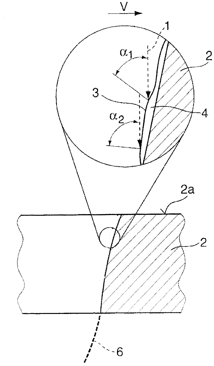
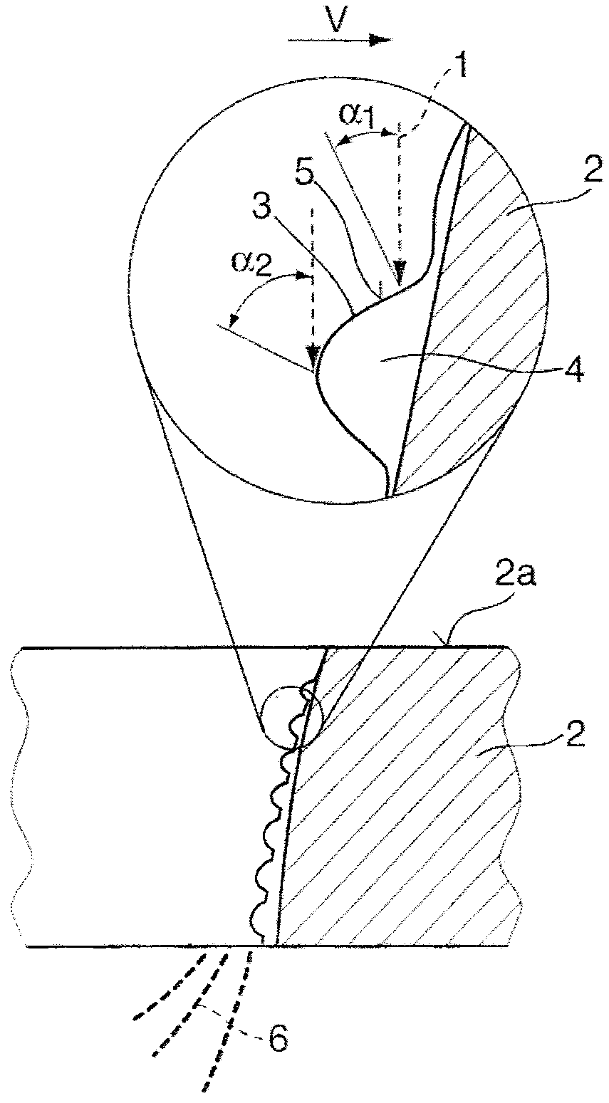
[0043] Such as Figure 1a , 1b In laser cutting with the aid of the laser beam 1, a part of the workpiece 2 is melted and / or vaporized at the working point, wherein, then, by the relative movement between the laser beam 1 and the workpiece 2 (cutting direction v) Consists of an irradiated front face across the material thickness of the workpiece 2 . This irradiated front side is marked with 3 and lies on the melt 4 . The laser beam 1 is directed at an angle of incidence in the range of approximately 70° to 110°, in particular approximately perpendicularly, at the workpiece surface 2 a facing it.

[0044] Figure 1a shows a conventional laser cutting process using a circularly polarized laser beam 1 with a wavelength of 10.6 μm, Figure 1b A conventional laser cutting process using a statistically polarized laser beam 1 with a wavelength of about 1 μm is shown. The melt 4 together with the irradiated front side 3 forms a corrugated surface structure which is significantly mo...


PUM

PropertyMeasurementUnit
wavelengthaaaaaaaaaa

Abstract

In a method for laser material processing a workpiece (2), in particular for laser cutting or laser welding, wherein by means of a laser beam (1) at least a part of the workpiece (2) is melted and / or vaporized and an irradiation front (3) is formed by adding a relative movement between the laser beam (1) and workpiece (2), according to the invention the surface structure of the irradiation front (3) is adjusted in accordance with a desired processing result. The surface structure of the irradiation front (3) can be adjusted, for example, by suitably selecting beam properties of the laser beam (1), in particular the polarization and / or beam profile.

Description

technical field [0001] The invention relates to a method for laser material processing of workpieces, in particular for laser cutting or laser welding, wherein at least a part of the workpiece is melted and / or vaporized by means of a laser beam, and by intervening between the laser beam and the workpiece relative movement to construct the irradiation front (Bestrahlfront). Background technique [0002] In laser material processing, different laser beam sources are used depending on the application and equipment availability. For example, for laser cutting operations, it is preferable to use CO with a laser wavelength of about 10 μm 2 Lasers, particularly solid-state lasers with a laser wavelength in the 1 μm range, are becoming more and more important in the case of laser fusion cutting due to the high feed rate increase and energy efficiency. [0003] In order to increase the efficiency of the methods used, attempts are generally made to maximize the energy incorporation ...

Claims


Application Information

Patent Timeline
Patent Type & Authority Applications(China)
IPC IPC(8): B23K26/38B23K26/06B23K26/073B23K26/14
CPCB23K26/08B23K26/38B23K26/0734B23K26/0608B23K26/0613B23K26/14B23K26/073B23K26/064
Inventor T·黑塞T·凯泽N·斯佩克T·黑克尔
Owner TRUMPF WERKZEUGMASCHINEN GMBH & CO KG
Learn More