
Method of realizing waveguide duplexer and multiplexer

A technology of multiplexer and duplexer, which is applied in the field of waveguide duplexer and multiplexer implementation, can solve the problems of high withstand power, low standing wave coefficient, small channel insertion loss, etc., and achieves high withstand power and standing wave. The effect of low coefficient and small channel insertion loss

Inactive Publication Date: 2013-07-31
王少夫
View PDF2 Cites 0 Cited by
  • Summary
  • Abstract
  • Description
  • Claims
  • Application Information

AI Technical Summary

Problems solved by technology

The method of the invention is simple, small in size, small in channel insertion loss, low in standing wave coefficient, and high in power, which is convenient and effective to overcome the problems of too complicated design steps and too large multiplexer volume in the traditional design process, and can ensure multiplexer to obtain the best multi-channel signal transmission efficiency

Method used


Image

  • Method of realizing waveguide duplexer and multiplexer
  • Method of realizing waveguide duplexer and multiplexer
  • Method of realizing waveguide duplexer and multiplexer

Examples


Embodiment 1

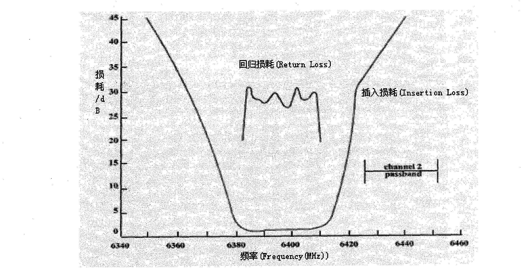
[0040] Design a Chebyshev multiplexer, the main technical indicators are: the center frequencies of the two channels are 6.3965GHz and 6.438GHz respectively, the bandwidth is 26MHz, and the return loss of the common end in the channel is required to be L r >26dB, insertion loss L in the passband of other channels a >35dB.

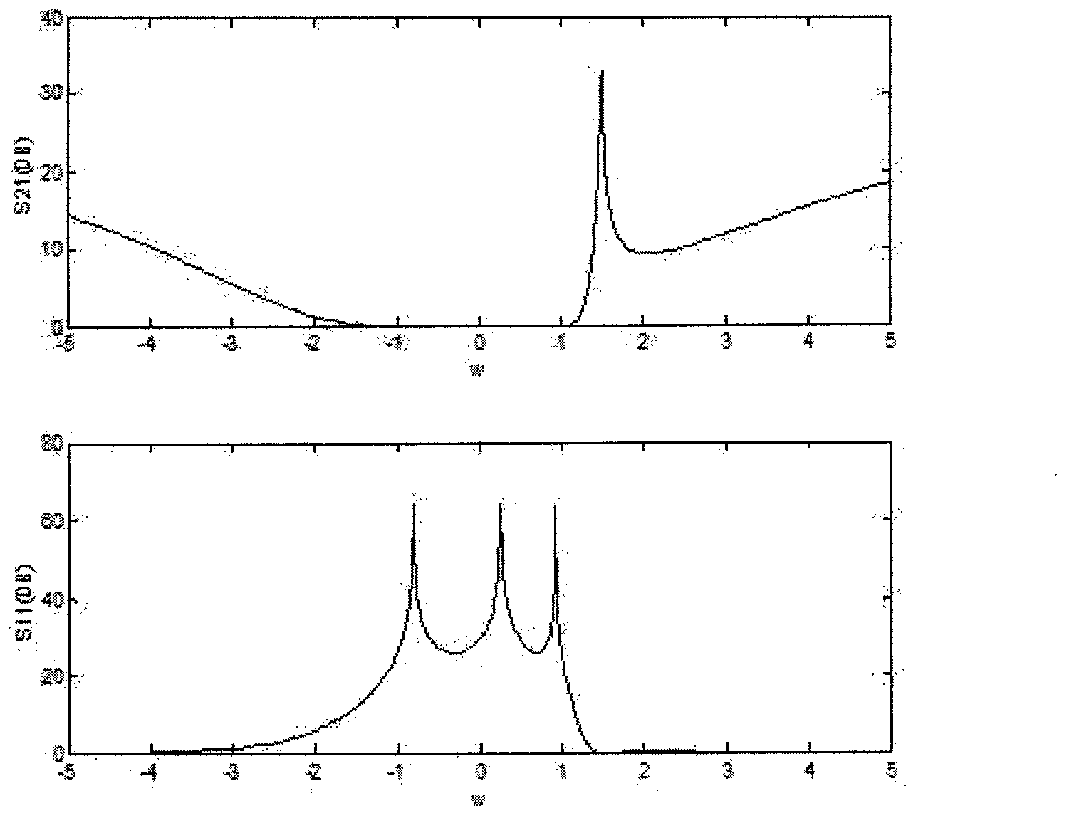
[0041] The adjusted values ​​of each component of the duplexer can be obtained directly by using equations (2) to (8). The waveguide structure is as follows: Figure 4 as shown,

[0042] Using the above frequency conversion technology and formula, you can determine the component values ​​of the designed bandpass filter and multiplexer, adjust the value of some components and connect them in series through matching inductors. The designed waveguide duplexer is as follows: Figure 4 As shown; the electrical isolation of each filter starting film is about π radians, and the relative difference of the resonant frequency of the waveguide cavity can be adjusted...

Embodiment 2

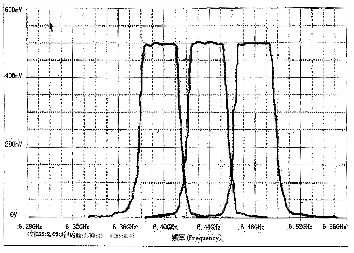
[0045] Design a Chebyshev multiplexer, the internal resistance of the signal source and the load impedance are both 50Ω, the center frequencies of the three channels are 6.3965GHz, 6.438GHz, and 6.4795GHz, and the bandwidth is 26MHz. The return loss of the common terminal in the passband is required to be L r >20dB, insertion loss L in the passband of other channels a >30dB.

[0046] Using the above frequency conversion technology and formula, the standard triplexer should be based on 4-section L r > 20dB prototype low-pass filter, adjust the value of some components and connect in series through matching capacitors or inductors, its amplitude-frequency characteristics are as follows: Image 6 shown;

[0047] from Image 6 It can be seen that the designed multiplexer fully meets the design requirements.

[0048] The designed waveguide duplexer and multiplexer have been successfully used in a pulsed multi-channel receiver. After FSK modulation and demodulation, the output r...


PUM


Abstract

In order to achieve multichannel transmission in a communication system, the invention provides a method of realizing a waveguide duplexer and a multiplexer. The method comprises the steps of providing a prototype low-pass filter, analyzing performance indexes of the duplexer and the multiplexer, establishing a network topology model, translating zero frequency points to obtain two or more low-pass filters with the same band-separation factor, and obtaining the target duplexer and the multiplexer by adjusting partial element values of channels and adding a part of compensating elements. The method is simple, the size is small, the channel insertion loss is low, the standing-wave ratio is low, the stand power is high, the method facilitates effectively solving the problems that the design steps are complicated and the multiplexer is oversized during the traditional design process; the multiplexer can obtain an optimal multichannel signal transmission effect; and the method can be widely used for the communication system.

Description

technical field [0001] The invention relates to a waveguide duplexer and a method for realizing the multiplexer. technical background [0002] In today's communication field, the development of various communication systems is extremely rapid, and multiplexers occupy an important position in communication equipment. Because in each frequency band, the frequency of various systems is crowded and multi-channel real-time multi-directional communication requirements, it is necessary to design multi-channel channel synthesis and separation devices at the front end of the equipment. Therefore, the multiplexer is one of the important circuit components. one. Especially with the development of large-scale integrated circuits, equipment miniaturization and functional diversification are required. Due to the mutual influence between channels, the design algorithm of multiplexers is very important for theoretical research and practical application. The designed filter faces the probl...

Claims


Application Information

Patent Timeline
Patent Type & Authority Applications(China)
IPC IPC(8): G06F17/50
Inventor 王少夫
Owner 王少夫
Learn More