Eureka AIR delivers breakthrough ideas for toughest innovation challenges, trusted by R&D personnel around the world.

Ammonia process flue gas treatment method for acidic tail gas and device

A sour tail gas and flue gas technology, applied in the fields of environmental protection, electric power, and chemical industry, can solve the problems of limited market capacity of by-product desulfurized gypsum, high operating costs, and consumption of sodium and alkali resources, so as to facilitate operation management, reduce investment costs, The effect of simple process

Active Publication Date: 2013-07-31
JIANGSU NEW CENTURY JIANGNAN ENVIRONMENTAL PROTECTION
View PDF4 Cites 62 Cited by
  • Summary
  • Abstract
  • Description
  • Claims
  • Application Information

AI Technical Summary

Problems solved by technology

[0006] At present, the calcium method is the most widely used flue gas desulfurization process for coal-fired boilers. The flue gas desulfurization equipment has high investment and high operating costs, especially the consumption of high-quality limestone resources, the limited market capacity of by-product desulfurization gypsum, and the need for wastewater treatment and discharge.
The sodium-alkali method is widely used in the treatment of acid tail gas, which consumes sodium-alkali resources. The market demand for by-products such as sodium sulfate is small, and it is difficult to achieve high added value, resulting in high operating costs and poor reliability.

Method used


Image

  • Ammonia process flue gas treatment method for acidic tail gas and device
  • Ammonia process flue gas treatment method for acidic tail gas and device
  • Ammonia process flue gas treatment method for acidic tail gas and device

Examples


Embodiment 2

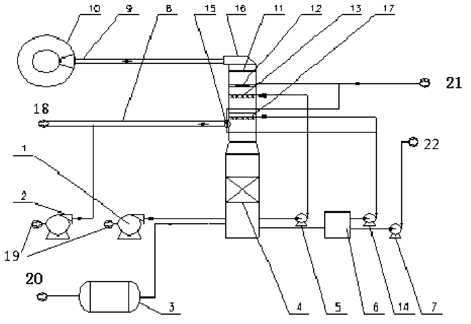
[0065] Example 2: figure 2 Sour tail gas ammonia desulfurization device in a natural gas plant

[0066] Total acid gas flue gas: 13375Nm 3 / h, flue gas temperature: 152°C, flue gas sulfur content 31443mg / Nm 3 , pressure 100000Pa. The reactant is ammonia water with a concentration of 15%.

[0067] Technological process and device: See the appendix for the technological process and device figure 2 . After the original flue gas is supplemented with normal temperature air through the blower 2, the sulfur dioxide content is reduced to 22000mg / Nm 3 , the temperature dropped to 115°C. The original flue gas is sprayed with process water and ammonium sulfate solution at the entrance of the absorption tower 15 (process water 0.2m 3 / h, ammonium sulfate solution 20m 3 / h) After the washing temperature drops to 70°C, it enters the absorption tower 16 to spray the absorption liquid. After entering the absorption tower 16, the flue gas is washed by three absorption liquid spray l...

Embodiment 3

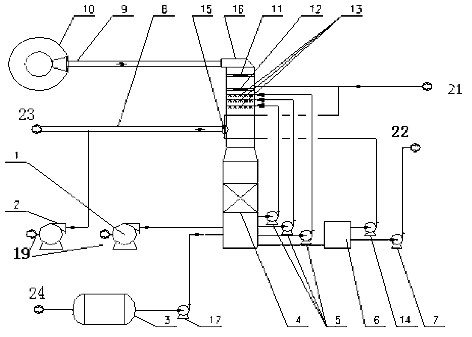
[0079] Example 3: A ammonia-based desulfurization device for Claus sulfur recovery tail gas in a coal chemical industry

[0080] The acid gas comes from the Claus sulfur recovery section of the coal chemical plant. It is produced by hydrogen sulfide gas after two-stage Claus sulfur recovery and then through the tail gas incinerator and waste heat boiler. The total amount of flue gas: 59912Nm 3 / h, flue gas temperature: 165°C, flue gas SO 2 Content 12600mg / Nm 3 , O 2 Content 2%, pressure 0.02MPa. The reactant is 99.6% liquid ammonia.

[0081] Process: See the attached flow chart of the device image 3 . The original flue gas is sprayed by process water at the entrance of the absorption tower 15 (process water 1m 3 / h) After the washing temperature drops to about 100°C, it enters the absorption tower 16. After entering the absorption tower 16, the flue gas is washed by the washing and cooling spray layer 2 in the absorption tower (ammonium sulfate solution 120m 3 / h), the ...

Embodiment 4

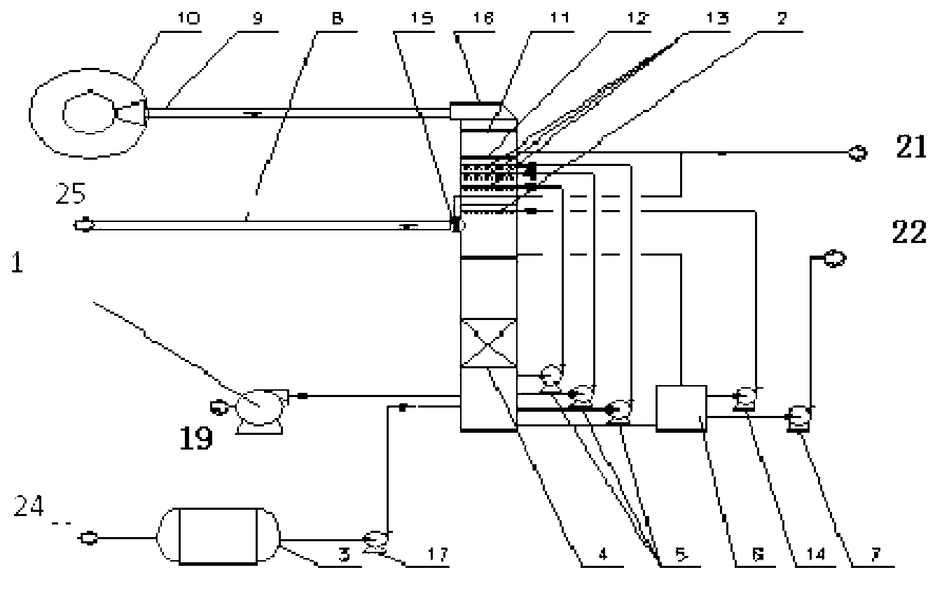
[0097] Example 4, a chemical acid tail gas ammonia desulfurization device

[0098] A chemical project produces sulfur-containing acid gas and organic waste liquid, which are burned in the incinerator, and the heat is recovered by the waste heat boiler to produce steam, which generates SO-containing 2 acidic exhaust. The total amount of flue gas of this acid gas: 11018Nm 3 / h, flue gas temperature: 350°C, flue gas SO 2 Content 2.57%, O 2 Content 6.22%, pressure 5000Pa.

[0099] The reactant is 99.6% liquid ammonia.

[0100] Process: See the attached flow chart of the device Figure 4 . After the original flue gas is supplemented with normal temperature air through the blower 10, the sulfur dioxide content is reduced to 6680mg / Nm 3 , the temperature dropped to 60°C. The original flue gas is sprayed by the process water layer 15 at the entrance of the absorption tower (process water 0.5m 3 / h) Washing temperature. And after entering the absorption tower 16, the flue gas...


PUM

PropertyMeasurementUnit
Volumeaaaaaaaaaa
Tower diameteraaaaaaaaaa

Abstract

The invention relates to an ammonia process flue gas treatment method for acidic tail gas. The method includes the steps of: 1) controlling the sulfur dioxide concentration of tail gas entering an absorption tower at a level of less than or equal to 30000mg / Nm<3>; 2) arranging process water in an absorption tower entrance flue or in the absorption tower or cooperating with a ammonium sulphate solution to perform spray cooling; 3) disposing an oxidation section in the absorption tower, setting an oxidation distributor at the oxidation section to achieve oxidation of a desulfurized absorption liquid; 4) arranging an absorption section in the absorption tower, utilizing an absorption liquid distributor in the absorption section to realize desulfurization spray absorption by an ammonia-containing absorption liquid, which is fed through an ammonia storage groove; 5) arranging a water washing layer at an absorption section upper part in the absorption tower, washing the absorption liquid in the tail gas by the water washing layer and reducing the absorption liquid escape; and 6) setting a demister at the upper part of the water washing layer in the absorption tower to control the mist drop content in the purified tail gas. Employment of the Claus sulfur recovery and ammonia process desulfurization integrated desulfurization technology in the coal chemical industry can reduce the investment cost of after-treatment, the process can be simpler, and factory environmental protection treatment can form an intensive advantage.

Description

technical field [0001] The invention relates to a purification technology and device for industrial flue gas such as acid tail gas (flue gas) in the production process of chemical industry (coal chemical industry). The flue gas desulfurization technology and device for chemical fertilizers belong to the technical fields of environmental protection, electric power, and chemical industry. Background technique [0002] Sulfur dioxide emitted in industrial processes is an important source of acid rain and sulfur dioxide pollution. In order to improve environmental quality and control sulfur dioxide emissions, desulfurization of industrial flue gas is imperative. [0003] Acid tail gas generally refers to the sulfur-containing gas produced in the process of chemical industry (coal chemical industry). After recovery of sulfur, phenol, naphthalene and other substances, it is sent to the tail gas incinerator to fully burn the organic matter and hydrogen sulfide in the tail gas. The...

Claims


Application Information

Patent Timeline
IPC IPC(8): B01D53/78B01D53/50B01D53/96C01C1/24
Inventor 徐长香罗静傅国光徐延忠
Owner JIANGSU NEW CENTURY JIANGNAN ENVIRONMENTAL PROTECTION
Why Eureka
Eureka Blog
Learn More