
Anticorrosion smoke waste heat recycling device of heat pipe structure

A technology of a flue gas waste heat and recovery device, applied in the field of waste heat recovery heat pipes, can solve the problems of increasing flow resistance, affecting the safe operation of equipment, affecting heat transfer effects, etc.

Active Publication Date: 2013-07-24
INST OF ENGINEERING THERMOPHYSICS - CHINESE ACAD OF SCI
View PDF7 Cites 10 Cited by
  • Summary
  • Abstract
  • Description
  • Claims
  • Application Information

AI Technical Summary

Problems solved by technology

[0002] In the flue gas waste heat recovery heat exchanger, because the flue gas contains more or less sulfur components, both sides of the heat exchange tube of the existing heat exchange equipment are gas-liquid heat exchange, due to the convective heat exchange on the gas and liquid sides Due to the huge difference in the coefficient, the temperature of the tube wall is closer to the temperature of the water side, so even when the temperature of the wall surface of the heat exchange tube is higher than the acid dew point, it will cause serious corrosion, which will affect the safe operation of the equipment
In order to reduce the cost of heat pipe heat exchangers, fins are usually used outside the heat pipes at present. However, fly ash will seriously affect the long-term heat transfer effect, which will lead to the deterioration of the heat transfer process, and at the same time lead to a significant increase in flow resistance. higher requirement

Method used


Image

  • Anticorrosion smoke waste heat recycling device of heat pipe structure
  • Anticorrosion smoke waste heat recycling device of heat pipe structure

Examples


Embodiment Construction

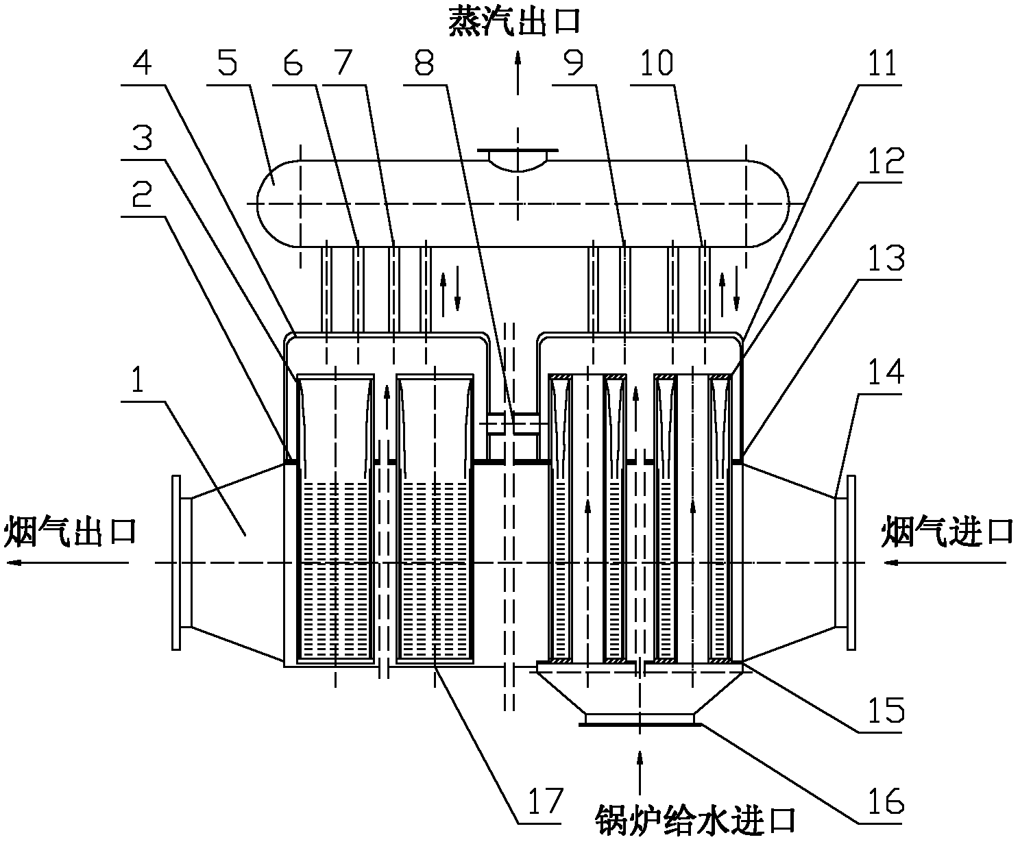
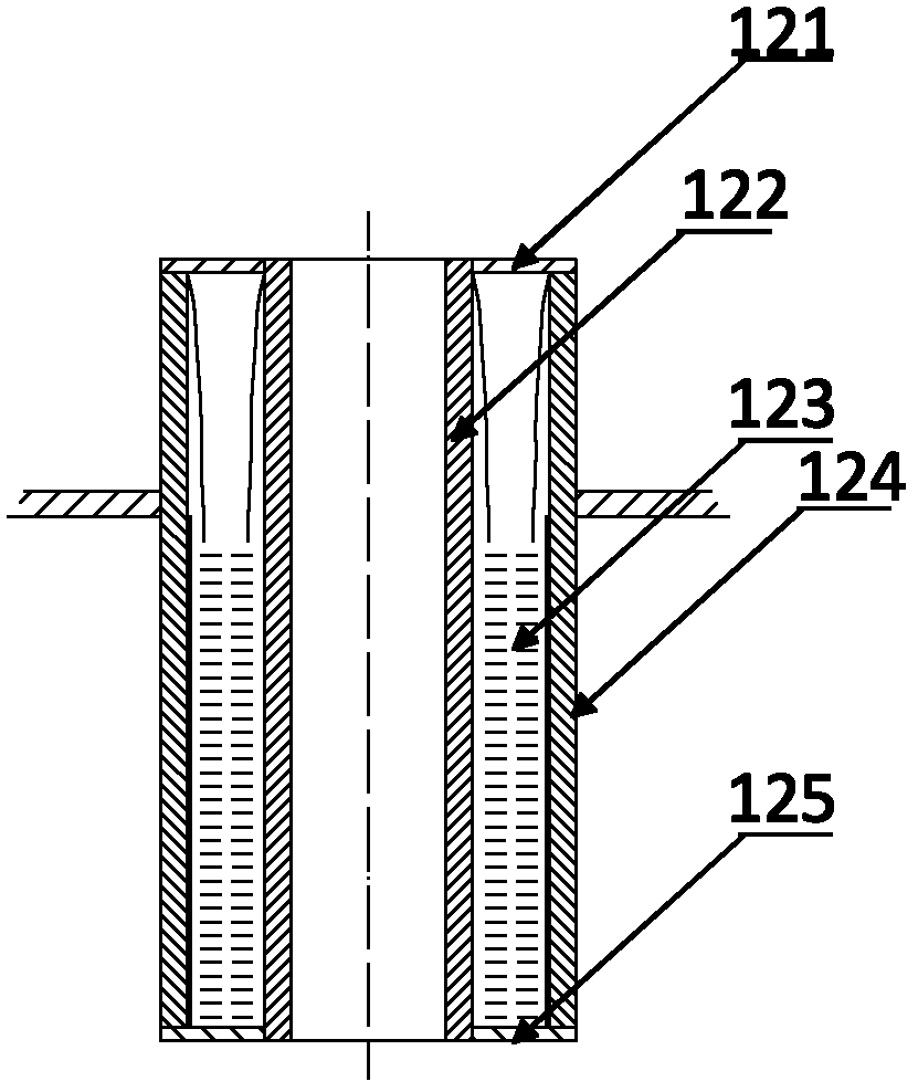
[0027] A corrosion-resistant flue gas waste heat recovery device with a heat pipe structure of the present invention adopts a sleeve-type heat pipe structure in the primary steam generator, which changes the cold water circulation path and form of the existing heat exchanger.

[0028] like figure 1 As shown, it is a corrosion-resistant flue gas waste heat recovery device with a heat pipe structure. The primary steam generator 11 is composed of tube bundles of sleeve-type heat pipes 12; the secondary steam generator 4 is composed of traditional heat pipes 3, and the middle partition 2 and 13. The secondary steam generator and the primary steam generator are divided into two parts respectively, and the connecting pipe 8 is used to communicate between the two parts. The gas-gathering generating chamber on the upper part of the partition is connected to the steam-gathering drum 5 by ascending pipes 7 and 10 and descending pipes 6 and 9; The tube flows into the steam generating ch...


PUM


Abstract

The invention discloses an anticorrosion smoke waste heat recycling device of a heat pipe structure, which relates to the heat pipe technology. The anticorrosion smoke waste heat recycling device consists of a primary vapor generator, a secondary vapor generator, a vapor collection bag, an ascending pipe and a descending pipe, and is used for producing saturated vapor; and the heat exchanging pipe of the primary vapor generator is of a bushing structure, and a plurality of bushing-type heat exchanging pipes form a heat pipe bundle. Supercooling water in the bushing-type inner pipe of the primary vapor generator exchanges heat with a wall with higher temperature, so that the heat conduction is reinforced, the system structure is more compact, and the weight is reduced. The anticorrosion smoke waste heat recycling device overcomes the defects of the traditional heat pipe heat exchanger adopting an unthreaded pipe that the specific area is small and the filling quantity of the working medium is large; and the temperature of the wall of a heat pipe is higher than the acid exposed point of the smoke waste heat fluid, so that the corrosion potential danger is eliminated. The anticorrosion smoke waste heat recycling device can be used for a waste heat recycling system with larger smoke quantity and the temperature of about 270 DEG C, can be typically used for recovering the waste heat of sulfur-contained smoke in the coking area and can realize the energy conservation and synergism.

Description

technical field [0001] The invention relates to the technical field of waste heat recovery heat pipes, and is a corrosion-resistant flue gas waste heat recovery device with a heat pipe structure. Background technique [0002] In the flue gas waste heat recovery heat exchanger, because the flue gas contains more or less sulfur components, both sides of the heat exchange tube of the existing heat exchange equipment are gas-liquid heat exchange, due to the convective heat exchange on the gas and liquid sides Due to the huge difference in the coefficient, the temperature of the tube wall is closer to the temperature of the water side. Therefore, even when the temperature of the wall surface of the heat exchange tube is higher than the acid dew point, it will cause serious corrosion, which will affect the safe operation of the equipment. In order to reduce the cost of heat pipe heat exchangers, fins are usually used outside the heat pipes at present. However, fly ash will serious...

Claims


Application Information

Patent Timeline
IPC IPC(8): F22B1/18F28D15/02
Inventor 袁达忠李玉华唐大伟
Owner INST OF ENGINEERING THERMOPHYSICS - CHINESE ACAD OF SCI
Learn More