Exhaust gas recovery system
A tail gas recovery and tail gas technology, used in ammonia preparation/separation, lighting and heating equipment, liquefaction, etc., can solve problems such as waste and underutilization of liquid nitrogen cooling capacity, reduce the risk of deflagration, and save supporting facilities Facility cost and operating cost, effect of reducing consumption
- Summary
- Abstract
- Description
- Claims
- Application Information
AI Technical Summary
Problems solved by technology
Method used
Image
Examples
Embodiment 1
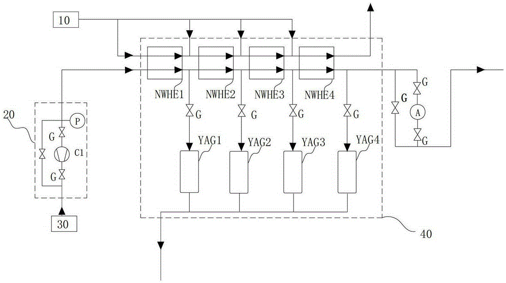
[0051] The tail gas recovery system of this embodiment is used to treat the tail gas generated by the tail gas pipe 30 of the MOCVD equipment. The tail gas can be separated, recovered or reused. Since nitrogen group elements are commonly used as the deposition gas source in MOCVD, the common tail gas components are mainly ammonia, doped with a certain amount of nitrogen and hydrogen. In this embodiment, the structure and operation method of this tail gas recovery system are introduced by taking the above tail gas components as an example.
[0052] Such as figure 1 As shown, the exhaust gas recovery system includes:
[0053] (1) Heat-absorbing fluid output terminal 10: commonly used heat-absorbing fluids can be liquid ammonia, liquid nitrogen, water or air; various heat-absorbing fluids can be adjusted depending on the actual process.
[0054] (2) The first compression device 20: it includes a compressor C1, a valve G and a pressure gauge P matched to the compressor C1. The...
Embodiment 2
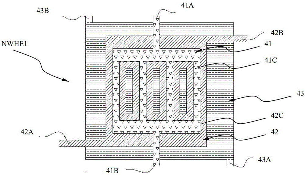
[0069] Compared with Embodiment 1, the tail gas recovery system of this embodiment has improved the structure of each NWHE, and increased the insulation channel 43, such as image 3 Shown:
[0070] The tail gas passage 41 and the heat absorption passage 42 of each NWHE are covered with a heat preservation passage 43, so that the heat absorption passage 42 is completely submerged in a heat preservation passage 43 filled with heat preservation liquid. The heat preservation channel 43 can be a pipeline completely covering the heat absorption channel 42 , or a box. It is also provided with an inlet 43A and an outlet 43B for the circulation of the heat preservation liquid, and the heat preservation channel entrance 43A located at the beginning end NWHE of the first heat exchange group 40 is connected to the heat preservation fluid output end 50 to accommodate a higher temperature heat preservation fluid; two adjacent heat preservation The passages 43 are connected end-to-end throu...
Embodiment 3
[0081] In this embodiment, the first compression device 20 of Embodiment 2 is added on the basis of the tail gas recovery system of Embodiment 2, such as Figure 5 shown. The introduction of the first compression device further ensures that the exhaust gas is liquefied at a higher temperature, and it can also ensure that the heat preservation fluid can work at a higher temperature, such as above 0°C, which reduces the difficulty of controlling the temperature of the heat preservation fluid and makes it possible for water to be used as a heat preservation fluid. The retained fluid in this embodiment is water, and its working temperature range is 0-50°C, which can be adjusted with the temperature control device.
[0082] Please refer to Embodiment 2 for other device structures.
[0083] The operation method of the tail gas recovery system of the present embodiment is as follows, as image 3 , 5 Shown:
[0084] Step 1, according to Figure 5 Assembling the NWHE: make the tai...
PUM
 Abstract
Description
Claims
Application Information
 - Generate Ideas
- Intellectual Property
- Life Sciences
- Materials
- Tech Scout
- Unparalleled Data Quality
- Higher Quality Content
- 60% Fewer Hallucinations
Browse by: Latest US Patents, China's latest patents, Technical Efficacy Thesaurus, Application Domain, Technology Topic, Popular Technical Reports.
© 2025 PatSnap. All rights reserved.Legal|Privacy policy|Modern Slavery Act Transparency Statement|Sitemap|About US| Contact US: help@patsnap.com


