Ojbective lens for optical pickup device and optical pickup device
A technology of optical pickup device and objective lens, which is applied in the direction of optics, optical components, TV system components, etc., and can solve the problems of increased cost and unfavorable miniaturization
- Summary
- Abstract
- Description
- Claims
- Application Information
AI Technical Summary
Problems solved by technology
Method used
Image
Examples
Embodiment )
[0307] Examples that can be used in the above-mentioned embodiments will be described below. Also, later (including table lens data), E (eg, 2.5×E-3) is sometimes used to represent powers of 10 (eg, 2.5×10 -3 ). In addition, the optical surface of the objective lens is formed as an aspheric surface that is axisymmetric around the optical axis and defined by the formulas in which the coefficients shown in the table are substituted into the formula 1.
[0308] [mathematical formula 1]
[0309] X ( h ) = ( h 2 / r ) 1 + 1 - ( 1 + κ ) ( ...
Embodiment 1)
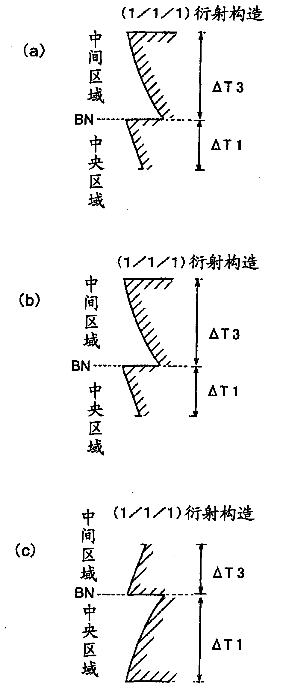
[0317] Table 1 shows the lens data of Example 1. This embodiment is an example in which the steps of the first foundation structure and the third foundation structure face the direction opposite to the optical axis, and the steps of the second foundation structure and the fourth foundation structure face the direction of the optical axis. The focal length of the BD is 2.2mm, and here the position is determined as a relatively short value. Figure 16 Shows the spacing of the individual infrastructures. exist Figure 16 In the diagram, the vertical axis represents the pitch P (mm), the horizontal axis represents the height from the optical axis, and the left side represents the central area and the right side represents the middle area with the boundary BN as a boundary. P1, P2, P3, and P4 are the values of the distances between the first foundation structure, the second foundation structure, the third foundation structure, and the fourth foundation structure closest to the bo...
Embodiment 2)
[0333] Table 2 shows the lens data of Example 2. This embodiment is an example in which the steps of the first foundation structure and the third foundation structure face the direction opposite to the optical axis, and the steps of the second foundation structure and the fourth foundation structure face the direction of the optical axis. The focal length of BD is a relatively short value like 1.77mm. Figure 17 Shows the spacing of the individual infrastructures. according to Figure 17 It can be seen that P1 and P3 are positive values, the absolute value of P3 is greater than P1, P2 and P4 are negative values, and the absolute value of P2 is greater than P4. Therefore, as shown in Table 6 described later, it can be seen that P4-P2>0 and P3-P1>0. in addition, Figure 11A diagram of longitudinal spherical aberration when the CD in Example 2 is used is shown. Such as Figure 11 As shown, spherical aberration occurs on the short side of the information recording surface of...
PUM
| Property | Measurement | Unit |
|---|---|---|
| thickness | aaaaa | aaaaa |
| thickness | aaaaa | aaaaa |
| refractive index | aaaaa | aaaaa |
Abstract
Description
Claims
Application Information
 - R&D Engineer
- R&D Manager
- IP Professional
- Industry Leading Data Capabilities
- Powerful AI technology
- Patent DNA Extraction
Browse by: Latest US Patents, China's latest patents, Technical Efficacy Thesaurus, Application Domain, Technology Topic, Popular Technical Reports.
© 2024 PatSnap. All rights reserved.Legal|Privacy policy|Modern Slavery Act Transparency Statement|Sitemap|About US| Contact US: help@patsnap.com


