Device and method for cool drying a gas

A technology of cooling and drying equipment, which is applied in the direction of chemical instruments and methods, mechanical equipment, separation methods, etc., can solve the problem of not getting the best cooling, and achieve the effect of small pressure dew point change and good drying effect

Active Publication Date: 2013-07-17
ATLAS COPCO AIRPOWER NV
View PDF3 Cites 2 Cited by
  • Summary
  • Abstract
  • Description
  • Claims
  • Application Information

AI Technical Summary

Problems solved by technology

[0019] This leads to the disadvantage that the gas to be dried is not optimally cooled for drying by the evaporator, which leads to a higher gas pressure dew point at the secondary part outlet of the heat exchanger, where the lowest Po...

Method used


Image

  • Device and method for cool drying a gas
  • Device and method for cool drying a gas
  • Device and method for cool drying a gas

Examples


Embodiment Construction

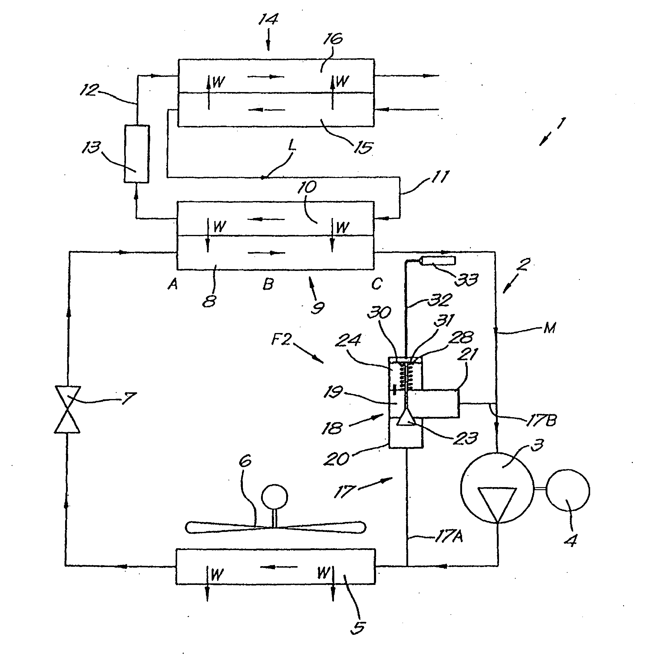
[0039] A known device 1 for cooling dry gas shown in FIG. 1 comprises a cooling line 2 containing a coolant which may be driven by a motor 4 or similar, preferably but not necessarily a constant speed motor. Compressor 3 circulates in the pipeline.

[0040] The flow direction of the coolant in the pipe is indicated by the arrow M. Upstream and downstream are defined according to the flow direction M.

[0041]In addition, the cooling line 2 comprises successively in the coolant flow direction: a condenser 5, which is connected to the outlet of the compressor 3 and cooled, for example, by means of a fan 6; an expansion device 7, for example in the form of an expansion valve; an evaporator 8, It is connected to the inlet of the aforementioned compressor 3 and forms part of a heat exchanger 9 having a primary part formed by an evaporator 8 and intended to drive the gas to be dried through a supply duct 11 in the direction of arrow L in order to Secondary section cooled by evapor...


PUM


Abstract

Device for cool drying a gas that consists of a closed cooling circuit (2) with a compressor (3), and which further in the direction of flow (M) of the coolant successively contains a condenser (5), an expansion means (7) followed by an evaporator (8), that constitutes the primary part of a heat exchanger (9) with a secondary part (10) through which the gas to be dried is guided, and whereby there is a bypass pipe (17) in the cooling circuit (2) that can be closed by means of a bypass valve (18) with a valve element (23) and a pressure-sensitive element (30) acting on it that is exposed to a local control pressure in the cooling circuit (2), whereby the control pressure pipe (38) is connected to the closed cooling circuit (2) upstream of the outlet of the evaporator (8).

Description

technical field [0001] The present invention relates to apparatus and methods for cooling dry gases. Background technique [0002] Cooling drying is used, for example, in compressors used to supply hot compressed gas, usually saturated with water. [0003] This compressed gas must be dried before it can be supplied to the pneumatic network, as moisture in the gas can be detrimental to components and tools in the pneumatic network, as moisture can cause corrosion or buildup in tools not designed for it water. [0004] Cooling drying is based on the principle that by cooling a gas saturated or partially saturated with water, water is removed from the gas as the water condenses and the condensed water is removed, after which the gas is heated again so that it is no longer saturated and Hence drier. [0005] For cooling and drying, a device is used which essentially comprises a closed cooling circuit containing a coolant which can be circulated in the circuit by a compressor ...

Claims


Application Information

Patent Timeline
IPC IPC(8): B01D53/26
CPCB01D53/265F25B49/022F25B2600/0261F25B41/20
Inventor B·吉特斯
Owner ATLAS COPCO AIRPOWER NV
Why Eureka
Try Eureka