A constant current drive controller and LED constant current drive circuit
A constant current drive and control circuit technology, applied in the direction of lamp circuit layout, electric light source, electrical components, etc., can solve the problems of constant current drive controllers such as many peripheral circuit devices, low circuit reliability, and exposed feedback pins. Achieve the effects of avoiding low reliability, improving circuit integration, and simplifying the structure of peripheral circuits
- Summary
- Abstract
- Description
- Claims
- Application Information
AI Technical Summary
Problems solved by technology
Method used
Image
Examples
Embodiment 1
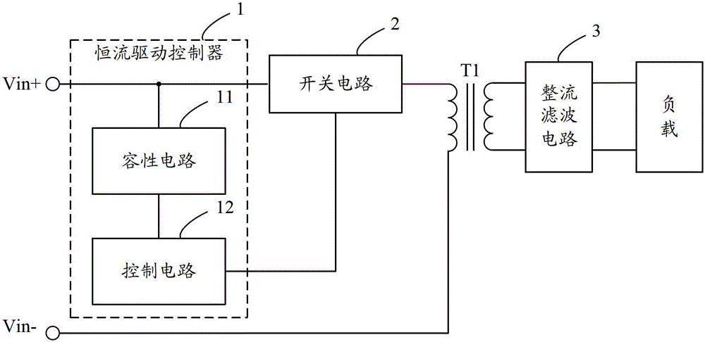
[0021] Embodiment 1 of the present invention proposes an LED constant current drive circuit, such as figure 2 As shown, for ease of description, only the part related to Embodiment 1 of the present invention is shown.
[0022] In detail, the LED constant current drive circuit includes a transformer T1, and also includes: a switch circuit 2, the voltage input end of the switch circuit 2 is connected to the positive pole Vin+ of the power supply, and the voltage output end of the switch circuit 2 is connected to the first end of the primary coil of the transformer T1 , the second end of the primary coil of the transformer T1 is connected to the negative pole Vin- of the power supply, and the switch circuit 2 is used to control whether the primary coil of the transformer T1 is energized or not through the switch state; the constant current drive controller 1 connected to the switch circuit 2; the rectification filter circuit 3. The input end of the rectification filter circuit 3...
Embodiment 2
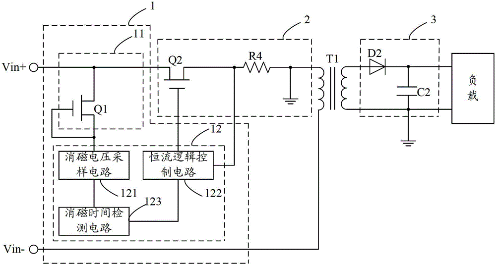
[0025] Embodiment 2 of the present invention proposes a LED constant current drive circuit, such as image 3 As shown, for ease of description, only the part related to Embodiment 2 of the present invention is shown. Different from the first embodiment, the second embodiment refines the circuit structure of the capacitive circuit 11 , the control circuit 12 , the switch circuit 2 and the rectification and filtering circuit 3 .
[0026] Specifically, the capacitive circuit 11 may include: a switch tube Q1, the voltage input terminal of the switch tube Q1 is used as the input terminal of the capacitive circuit 11 and connected to the voltage input terminal of the switch circuit 2, and the voltage output terminal of the switch tube Q1 is used as the capacitive circuit The output end of the control circuit 11 is connected to the input end of the control circuit 12, and the capacitance in the capacitive circuit 11 is formed by the source-drain parasitic capacitance of the switch tr...
Embodiment 3
[0033] Embodiment 3 of the present invention proposes a LED constant current drive circuit, such as Figure 4 As shown, for ease of description, only the part related to Embodiment 3 of the present invention is shown. Wherein, the circuit structures of the control circuit 12 , the switch circuit 2 and the rectification and filtering circuit 3 are the same as those in the second embodiment, and will not be repeated here.
[0034] Different from Embodiment 2, in Embodiment 3, the capacitive circuit 11 may include: a capacitor C3, one end of the capacitor C3 is used as the input end of the capacitive circuit 11 and connected to the voltage input end of the switch circuit 2, and the other end of the capacitor C3 is used as a capacitor The output end of the resistance circuit 11 is connected to the input end of the control circuit 12 .
PUM
 Abstract
Description
Claims
Application Information
 - R&D
- Intellectual Property
- Life Sciences
- Materials
- Tech Scout
- Unparalleled Data Quality
- Higher Quality Content
- 60% Fewer Hallucinations
Browse by: Latest US Patents, China's latest patents, Technical Efficacy Thesaurus, Application Domain, Technology Topic, Popular Technical Reports.
© 2025 PatSnap. All rights reserved.Legal|Privacy policy|Modern Slavery Act Transparency Statement|Sitemap|About US| Contact US: help@patsnap.com


