Straight waveguide phase modulator

A phase modulator and straight waveguide technology, applied in the direction of instruments, nonlinear optics, optics, etc., can solve the problems of increased coupling process complexity, unfavorable signal processing, and decreased processing efficiency, so as to improve system reliability and improve production Effect of improving processing efficiency and degree of polarization

Active Publication Date: 2013-07-10
THE 44TH INST OF CHINA ELECTRONICS TECH GROUP CORP
View PDF4 Cites 10 Cited by
  • Summary
  • Abstract
  • Description
  • Claims
  • Application Information

AI Technical Summary

Problems solved by technology

It can be seen from the schematic diagram that the fiber optic current transformer is mainly composed of a light source, a photodetector ( figure 2 Middle PIN), polarization maintaining fiber coupler, linear polarizer, first polarization maintaining fiber, direct waveguide phase modulator (i.e. titanium diffused lithium niobate phase modulator), second polarization maintaining fiber, λ / 4 wave plate , a sensing fiber optic ring and a reflector; among them, related to the problems solved by the present invention are: 1) the linear polarizer and the straight waveguide phase modulator are split structures, and the total volume of the device is relatively large; 2) the line The polarizing polarizer and the direct waveguide phase modulator are connected through the first polarization maintaining fiber. Under the existing technical conditions, the polarization maintaining performance of the 2-meter-long polarization maintaining fiber is only 35dB, and the polarization maintaining performance of the polarization maintaining fiber is still It will continue to decrease as the length increases, which leads to the polarization of the linearly polarized light that finally enters the straight waveguide phase modulator is less than 35dB, which is very unfavorable for subsequent signal processing
[0004] Recent studies have shown that the polarization extinction ratio of the lithium niobate optical waveguide processed by the annealing proton exchange process can reach more than 80dB, and this lithium niobate optical waveguide is used as a polarizer (that is, a lithium niobate polarizer chip) Linearly polarized light with a high degree of polarization can be obtained, and it can be directly coupled with the titanium-diffused lithium niobate phase modulator, so that the linearly polarized light with a high degree of polarization can be directly injected into the titanium-diffused lithium niobate phase modulator without loss of polarization In this way, the polarization-maintaining fiber between the polarizer and the phase modulation device is omitted; but in practical applications, due to the need to adjust the polarization angle of the lithium niobate polarizer chip, it is necessary to adjust the titanium in the coupling process The coupling angle of the diffused lithium niobate phase modulator and the lithium niobate polarizer chip is adjusted. Since the coupling quality of the titanium diffused lithium niobate phase modulator and the lithium niobate polarizer chip needs to be monitored in real time during the coupling process, Therefore, the coupling process requires manual operation, and the operator has to monitor the coupling effect and adjust the coupling angle during the operation, which leads to a significant increase in the complexity of the coupling process and a significant decrease in processing efficiency

Method used


Image

  • Straight waveguide phase modulator
  • Straight waveguide phase modulator
  • Straight waveguide phase modulator

Examples


Embodiment Construction

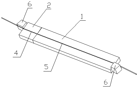
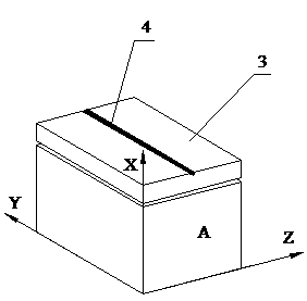
[0016] A direct waveguide phase modulator, comprising a titanium diffused lithium niobate phase modulator 1, the input end face of the titanium diffused lithium niobate phase modulator 1 is coupled and bonded to the end face of a lithium niobate polarizer chip 2; The lithium niobate polarizer chip 2 is composed of a lithium niobate wafer 3 and a polarizing waveguide 4 formed on its surface by a proton exchange annealing process, the surface of the structure where the polarizing waveguide 4 is located forms a first waveguide surface, The polarizing angle of the polarizing waveguide 4 to the input light is at an angle of 45° to the first waveguide surface, and the surface of the structure where the phase modulation waveguide 5 on the titanium-diffused lithium niobate phase modulator 1 is located forms the second waveguide surface, and the first waveguide face is flush with the second waveguide face.


PUM


Abstract

A straight waveguide phase modulator comprises a titanium-diffused lithium niobate phase modulator. The straight waveguide phase modulator is characterized in that the end face of the input end of the titanium-diffused lithium niobate phase modulator is adhered with the end face of a lithium niobate polarizer chip in a coupling manner; the lithium niobate polarizer chip comprises a lithium niobate wafer and a polarizing waveguide formed on the surface of the lithium niobate wafer; a first waveguide surface is formed on the surface of a structure of the polarizing waveguide, and a 45-degree included angle is formed between the polarizing angle of the polarizing waveguide to input light and the first waveguide surface; a second waveguide surface is formed on the surface of a structure of a phase modulation waveguide; and the first waveguide surface is flush with the second waveguide surface. The straight waveguide phase modulator has the advantages that a polarizing device and a phase modulation device are integrated, so that the size of the straight waveguide phase modulator is greatly reduced, complexity of coupling technique is reduced, and production and processing efficiency is improved. Since polarization maintaining optical fiber connection between the polarizing device and the phase modulation device is omitted, degree of polarization is greatly increased (larger than 80 decibels), and meanwhile, system reliability is improved.

Description

technical field [0001] The invention relates to a phase modulator, in particular to a straight waveguide phase modulator. Background technique [0002] The fiber optic current transformer (FOCT), which borrows from the optical fiber gyroscope photoelectric signal processing technology, constructs a digital closed-loop feedback system through a high-speed signal processing unit and an electro-optic phase modulator, which can measure the non-mutual effects caused by the magnetic field Faraday effect in the light wave loop in real time. This makes FOCT have the advantages of wide measurement range and good dynamic characteristics, which solves the problems of hysteresis saturation and waveform distortion in traditional electromagnetic current transformers, and adapts to modern power systems. The need for reliability of current measurements. [0003] figure 2 It is a schematic diagram of the composition and structure of a typical fiber optic current transformer. The essenc...

Claims


Application Information

Patent Timeline
Patent Type & Authority Applications(China)
IPC IPC(8): G02F1/035
Inventor 华勇舒平田自君张鸿举黄健王超
Owner THE 44TH INST OF CHINA ELECTRONICS TECH GROUP CORP
Why Eureka
Try Eureka