
Aqueous humor drainage implant

A technology of implants and aqueous humor, applied in wound drainage devices, ophthalmic surgery, etc., can solve the problems of high incidence of hypoocular pressure, achieve the effects of controlling the formation of blood coagulation, expanding volume, and reducing irritation

Inactive Publication Date: 2013-07-10
CAPITAL UNIVERSITY OF MEDICAL SCIENCES
View PDF6 Cites 12 Cited by
  • Summary
  • Abstract
  • Description
  • Claims
  • Application Information

AI Technical Summary

Problems solved by technology

Although restrictive aqueous humor drainage implants can lower and maintain intraocular pressure more smoothly than non-restrictive aqueous humor drainage implants, current restrictive aqueous humor drainage implants still have some structural defects , not all restrictive aqueous humor drainage implants can restrict the outflow of aqueous humor, and the incidence of shallow anterior chamber and low intraocular pressure is still high

Method used


Image

  • Aqueous humor drainage implant
  • Aqueous humor drainage implant
  • Aqueous humor drainage implant

Examples


Embodiment 1

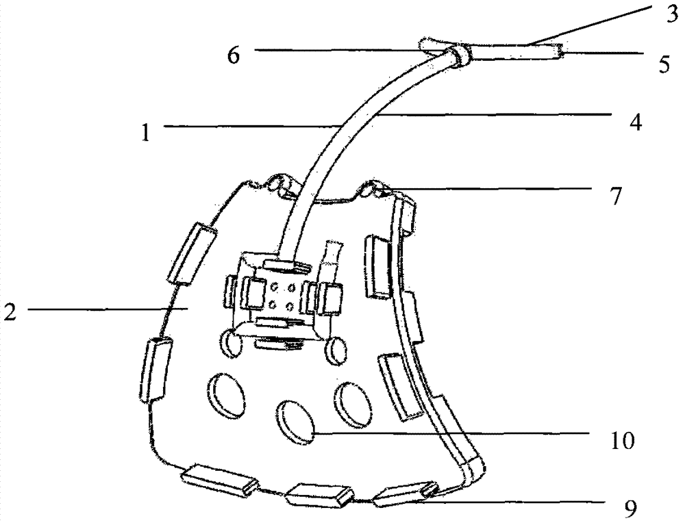
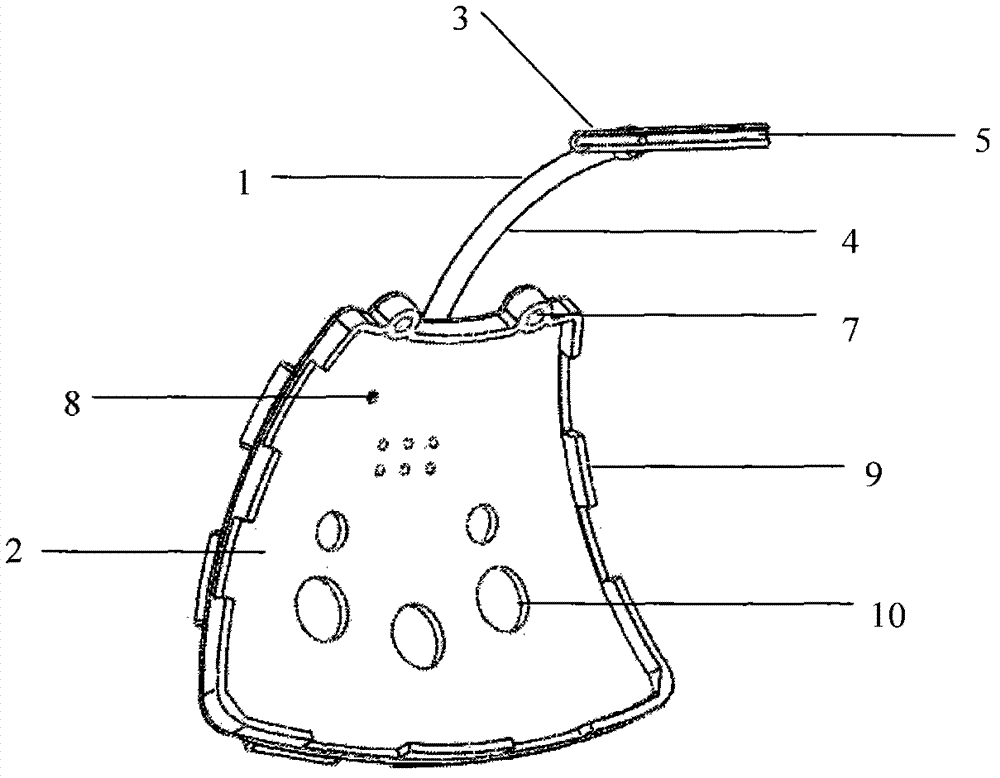
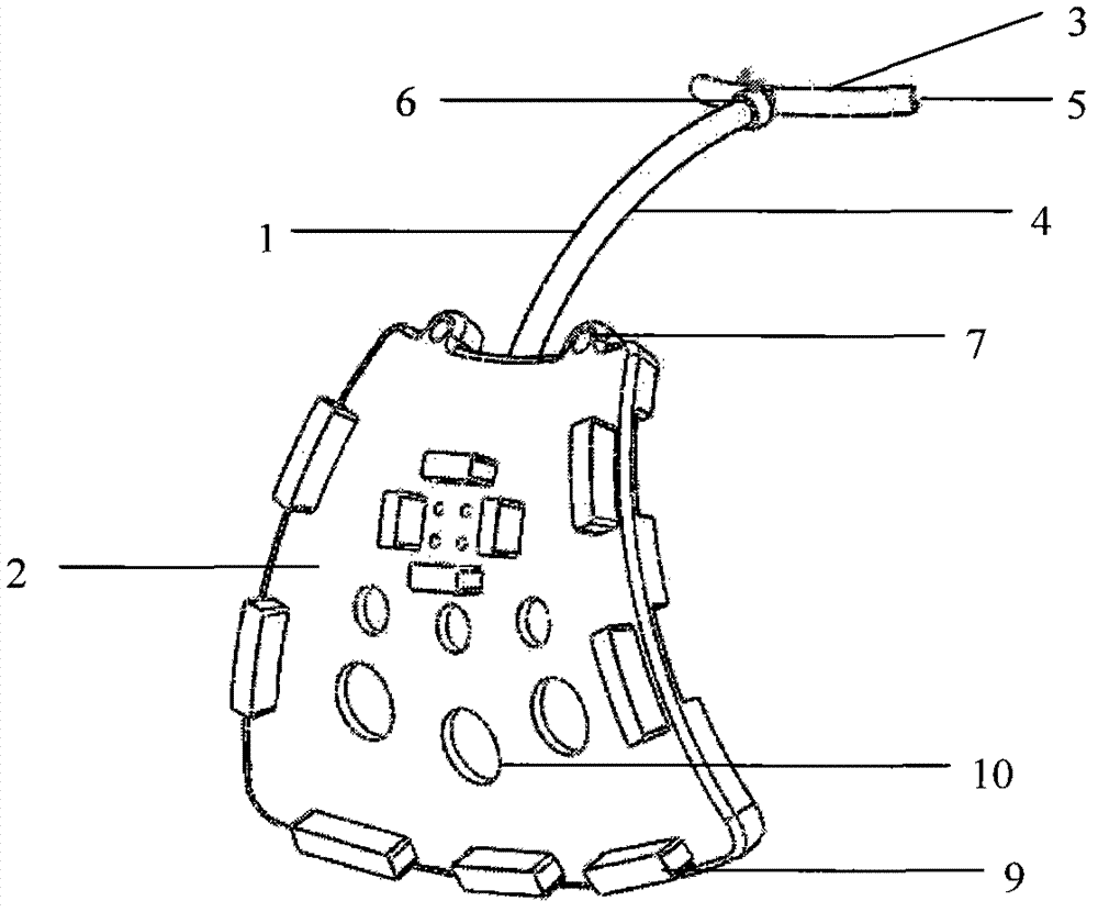
[0035] Embodiment 1: as figure 1 As shown, the drainage tube of the new aqueous humor drainage implant is a T-shaped silicone tube, and its specifications can be selected from an outer diameter of 0.6mm and an inner diameter of 0.3mm. The transverse tube of the T-shaped drainage tube has a curvature radius of about 5.85mm similar to that of the corneoscleral limbus. There is a drainage groove on the surface of the horizontal tube in the room of the drainage tube in contact with the aqueous humor. The fan-shaped drainage plate is a curved surface, which is suitable for the outer surface of the sclera. Its specification can be similar to that of the sclera. The radius of curvature is about 12mm, and the surface area of ​​the drainage plate is 195.38mm. 2 , 1.2mm high. The long drainage tube is coiled along the ridges to form an aqueous humor outflow control system, and the ridge height is 0.8mm.

Embodiment 2

[0036] Embodiment 2: as image 3 As shown, the specifications of the drainage tube and the drainage plate can be selected from the specifications in Example 1. The double-leaf flap valve is consistent with the specifications of the drainage tube, with a leaflet diameter of 0.3mm and a thickness of 0.2mm.


PUM

PropertyMeasurementUnit
Surface areaaaaaaaaaaa
Outer diameteraaaaaaaaaa
The inside diameter ofaaaaaaaaaa

Abstract

The invention relates to an aqueous humor drainage implant. The aqueous humor drainage implant comprises a T-shaped drainage tube and a drainage disk, which are connected, wherein a liquid inlet transverse tube of the T-shaped drainage tube has the same curvature radius as that of a limbus corneae; a drain groove is formed at the contact surface between the liquid inlet transverse tube and an aqueous humor; an aqueous humor outflow controller is formed by a drainage long tube of the T-shaped drainage wrapped along protuberant ridges of the drainage disk or by utilizing a double-leaf flap valve, so as to avoid or reduce the occurrence of shallow anterior chamber and ocular hypotension in early period of post operation; a liquid outlet end of the drainage tube is matched with an anti-fall off clamp on the drainage disk; the liquid inlet transverse tube and the drainage long tube are integrally formed, or abutted through a leak-proof clamp so as to reduce the cost of a secondary surgery and facilitate the replacement of the drainage tube when an operation fails due to blockage of the drainage tube; a 5-Fu lipidosome biological filtering membrane is attached to the inner wall of the drain groove so as to effectively control the formation of blood coagulation as well as the scarring of a surgical area; suture holes are formed at the front end of the drainage disk; and aqueous humor traffic holes are formed in the center of the drainage disk and the protuberant ridges are arranged at the periphery of the drainage disk. The novel aqueous humor drainage implant is applicable to the treatment of glaucoma, the volume of a filtering area is enlarged, and the drainage tube can be replaced, thereby reducing the difficulty of the secondary surgery.

Description

technical field [0001] The invention relates to a medical artificial implant, in particular to an aqueous humor drainage implant suitable for establishing an effective filtering channel after glaucoma surgery, especially for refractory glaucoma. Background technique [0002] Glaucoma is a common and difficult eye disease with rapid onset, high hazards, and blindness at any time. Glaucoma accounts for the second blinding eye disease in my country. It is characterized by intermittent or persistent increases in intraocular pressure that exceed the eyeball's tolerance. The degree of exposure will cause damage to various parts of the eyeball and visual function, resulting in optic atrophy, narrowing of the field of vision, loss of vision, and eventually blindness. Glaucoma filtration surgery is currently an important operation when glaucoma drugs cannot control intraocular pressure. The purpose of filtration surgery is to create a fistula that allows aqueous humor to flow out of t...

Claims


Application Information

Patent Timeline
IPC IPC(8): A61F9/007A61M27/00
Inventor 刘志成全海英张昆亚曹海勇黄跃
Owner CAPITAL UNIVERSITY OF MEDICAL SCIENCES
Learn More