
Switch equipment

A switch and device technology, applied in the field of data communication, can solve the problems of reducing the synchronous download speed and efficiency of table items, high implementation complexity, and increased system startup time, so as to reduce the time for software update and maintenance, improve processing efficiency, The effect of reducing startup time

Active Publication Date: 2013-07-03
MAIPU COMM TECH CO LTD
View PDF6 Cites 18 Cited by
  • Summary
  • Abstract
  • Description
  • Claims
  • Application Information

AI Technical Summary

Problems solved by technology

[0009] From the perspective of the system, the above-mentioned main functions (2) (3) (4) all involve the distributed architecture of the software, which leads to the problem that the implementation complexity of the software required to run on the switch device is too high and The inefficiencies are as follows:
[0010] (a) The implementation complexity of the distributed control software required by this hardware architecture increases, whether it is the synchronization of two-layer forwarding table items or three-layer forwarding table items, the sending and receiving of control messages, and the distributed processing of control protocols , or distributed error handling, which significantly increases the complexity of software design;
[0011] (b) Due to the different switching characteristics and table entry sizes supported by different packet processing chips (typically switch ASIC chips), this system is not conducive to the design of high-end switch equipment with a mixed architecture of different packet processing chips; In devices with a mixed architecture, the complexity of distributed software processing increases. In particular, it is necessary to perform individualized software processing for the size of L2 and L3 forwarding entries, different contents, and even different functional characteristics of different chips, resulting in The complexity of managing the packet processing chips on different LPUs from the MPU through software increases, and it is impossible to optimize the distributed communication between the MPU and the LPU, which greatly reduces the speed and efficiency of synchronous downloading of entries. Greatly increases the convergence time of the network, and will also reduce the stability of the network
[0012] (c) Due to the existence of the LPU and SFU control processors, the startup time of the entire system is greatly increased, and the time spent in upgrading and updating the software system is also greatly increased. Correspondingly, this also greatly increases the failure recovery time of this system , the processing efficiency is low, which essentially reduces the reliability index of the entire system

Method used


Image

  • Switch equipment
  • Switch equipment
  • Switch equipment

Examples


Embodiment Construction

[0057] The present invention will be further described in detail below with reference to the accompanying drawings and specific embodiments.

[0058] The invention mainly adopts the PCIE technology to realize the communication connection and information exchange of the control plane of the switch device.

[0059] As a high-speed serial I / O bus technology, PCIE is developing rapidly. Currently, the bandwidth of each lane of PCIE 3.0 can reach up to 8.0Gbps, and it can support up to x16Lane; it is worth noting that in the process of PCIE bus technology development In the PCIE 2.1 and 3.0 standards, not only the bus bandwidth rate is improved, but also the functional characteristics are greatly enhanced; in the PCIE 2.1 and 3.0 standards, the high availability (HA) or failover (FailOver) capabilities, The enhancement of the ability of the PCIE bus makes the PCIE bus have the ability to be applied in the equipment with high requirements of high reliability. At present, it is wide...


PUM


Abstract

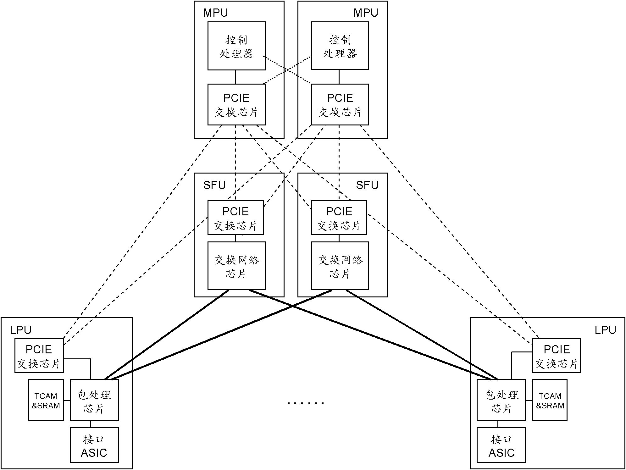
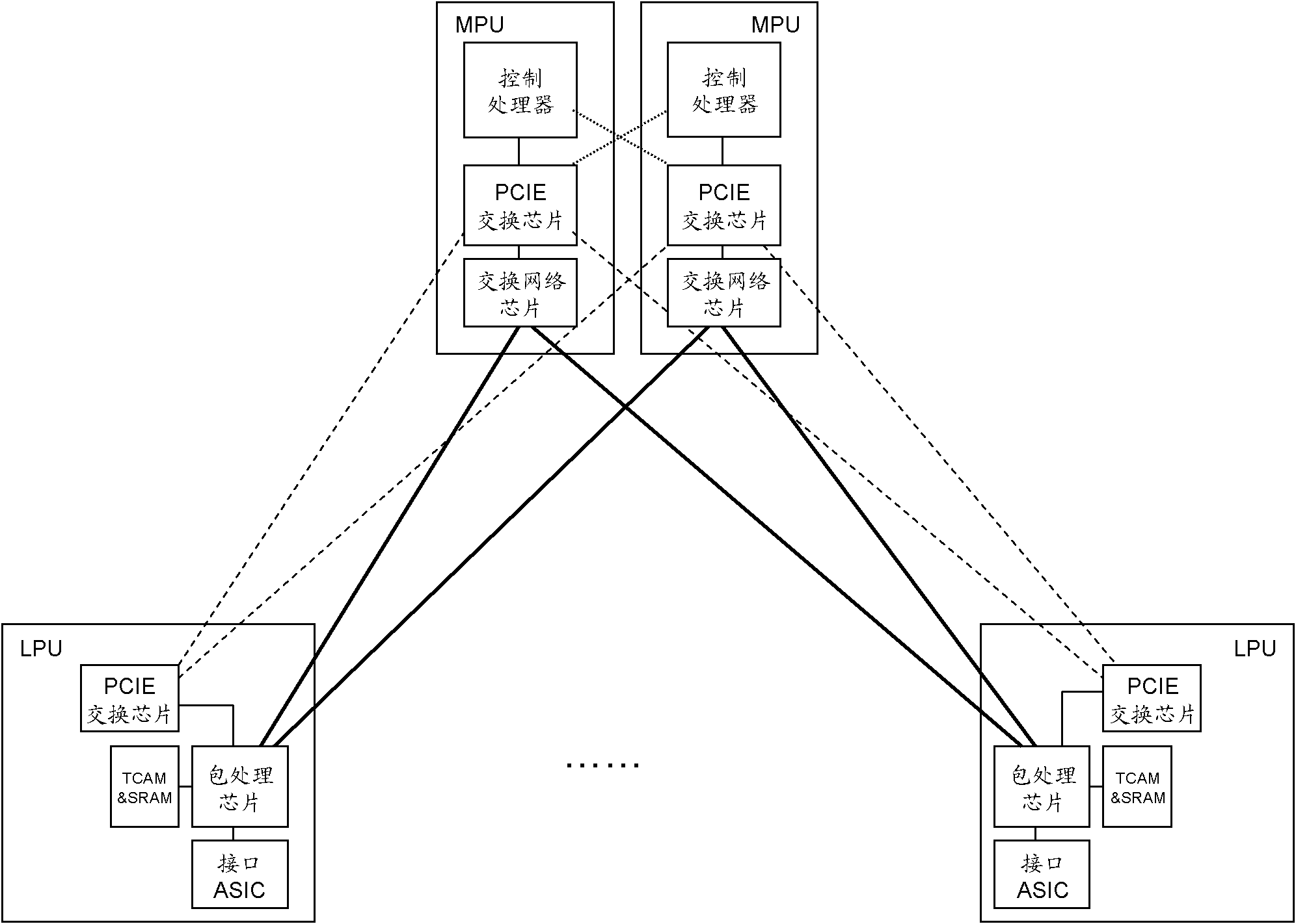
The invention discloses switch equipment which comprises master control cards, switching cards and a line card, wherein the master control cards comprise control processors and PCIE (peripheral component interface express) switching chips; the switching cards comprise PCIE switching chips and switched network chips; the line card comprises a PCIE switching chip and a packet processing chip; in the master control cards, the PCIE switching chips are connected with the control processors by up PCIE interfaces, and connected with up PCIE interfaces of the PCIE switching chips of the line card and the switching cards by down PCIE interfaces and control buses; the PCIE switching chips of the line card and the switching cards are connected with a packet processing chip and a switched network chip of a board card by down PCIE interfaces respectively; PCIE networks form a centralized control plane; and the packet processing chip of the line card is connected with the switched network chips of the switching cards by an internal data bus to form a distributed data plane. With the adoption of the switch equipment, the realization complexity of software required to run on the switch equipment can be reduced, and the processing efficiency of the switch equipment is improved.

Description

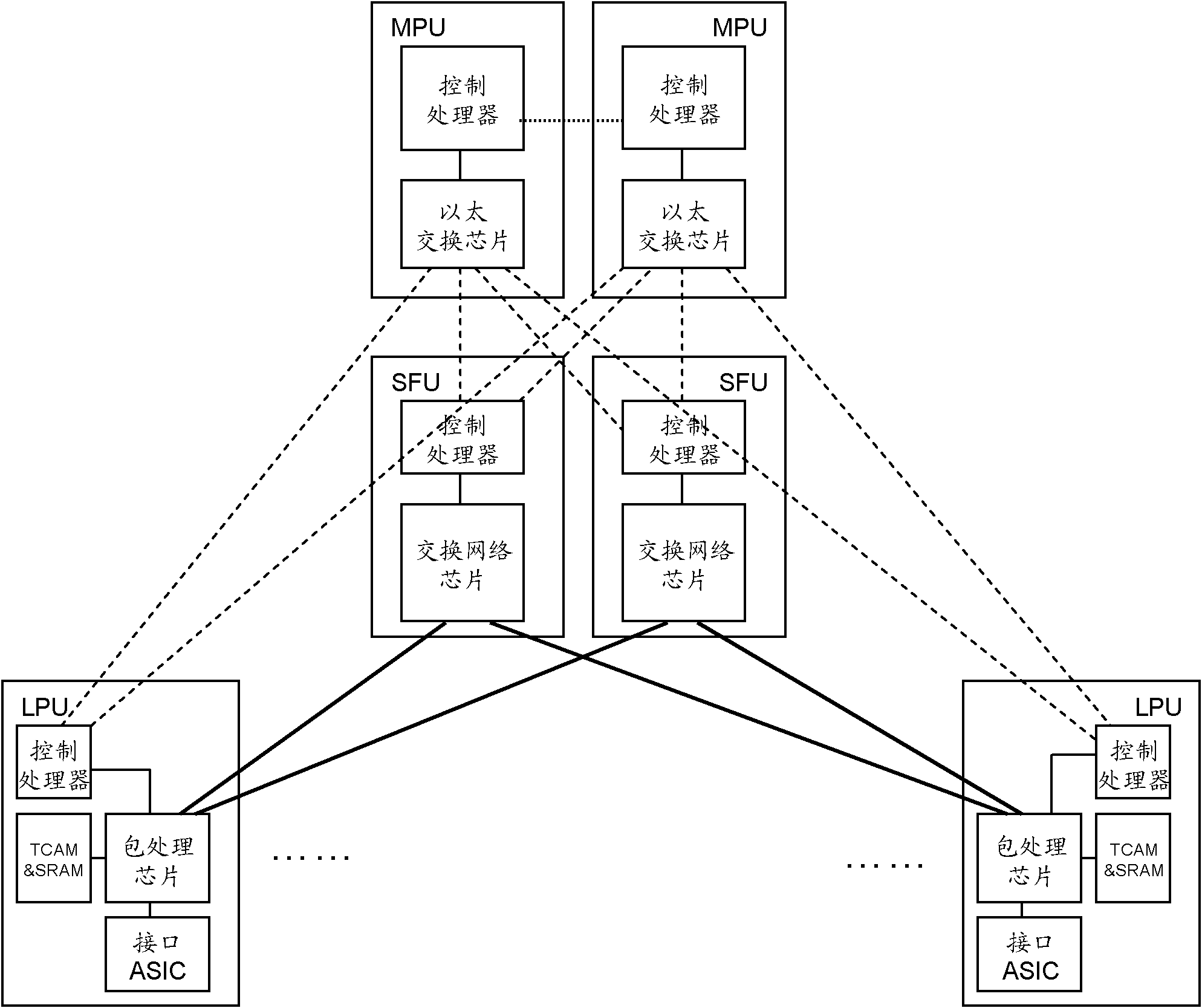
technical field [0001] The present invention relates to data exchange technology in the field of data communication, in particular to a switch device. Background technique [0002] For a long time, when implementing high-end switch devices based on distributed forwarding, most of the industry adopts the system architecture of distributed data forwarding and distributed protocol control. figure 1 It is a schematic diagram of the implementation of a typical high-end distributed switch device in the industry. see figure 1 , the distributed switch device includes two mutual backup main control cards (MPU), at least two mutual backup and load balancing switch cards (SFU), and at least one interface line card (LPU), wherein the One of the two MPUs is active and the other is standby, and the two or more SFUs are mutually redundant and traffic balanced. The MPU includes a control processor and an Ethernet switch chip, the SFU includes a control processor and a switch network (Fab...

Claims


Application Information

Patent Timeline
Patent Type & Authority Applications(China)
IPC IPC(8): H04L12/931
Inventor 戴俊文
Owner MAIPU COMM TECH CO LTD
Learn More