
Building with triangular solar photovoltaic conversion structure

A photoelectric conversion, solar panel technology, applied in the direction of solar thermal power generation, solar thermal energy, solar thermal collectors, etc. question

Inactive Publication Date: 2013-07-03
王广武
View PDF0 Cites 12 Cited by
  • Summary
  • Abstract
  • Description
  • Claims
  • Application Information

AI Technical Summary

Problems solved by technology

[0002] The current building-integrated photovoltaics is more about moving the installation method of the inclined plane structure of the ground power station directly to the roof or the wall, which not only brings hidden dangers to building safety, but also the stability of the photovoltaic system itself. Destroy the overall aesthetics of the building to a certain extent
Due to the opacity of the photovoltaic system, two functions of power generation and daylighting cannot be realized
Since the solar panel is a single-layer structure, it does not have the function of heat preservation and cannot achieve building energy saving
[0003] There is no wind dust or snow removal device on the solar panel of the existing solar power generation device, because the light-transmitting outer panel has been impacted by wind and sand for a long time, gas corrosion, dust or snow cover, reducing the sunlight intensity of the light-transmitting outer panel, reducing The photoelectric conversion efficiency of solar power generation devices causes waste of resources
[0004] There is no wind cooling device on the solar panel of the existing solar power generation device. When the temperature of the solar panel rises above 35 degrees, the photoelectric conversion efficiency and service life of the solar panel will be reduced.

Method used


Image

  • Building with triangular solar photovoltaic conversion structure
  • Building with triangular solar photovoltaic conversion structure
  • Building with triangular solar photovoltaic conversion structure

Examples


Embodiment 1

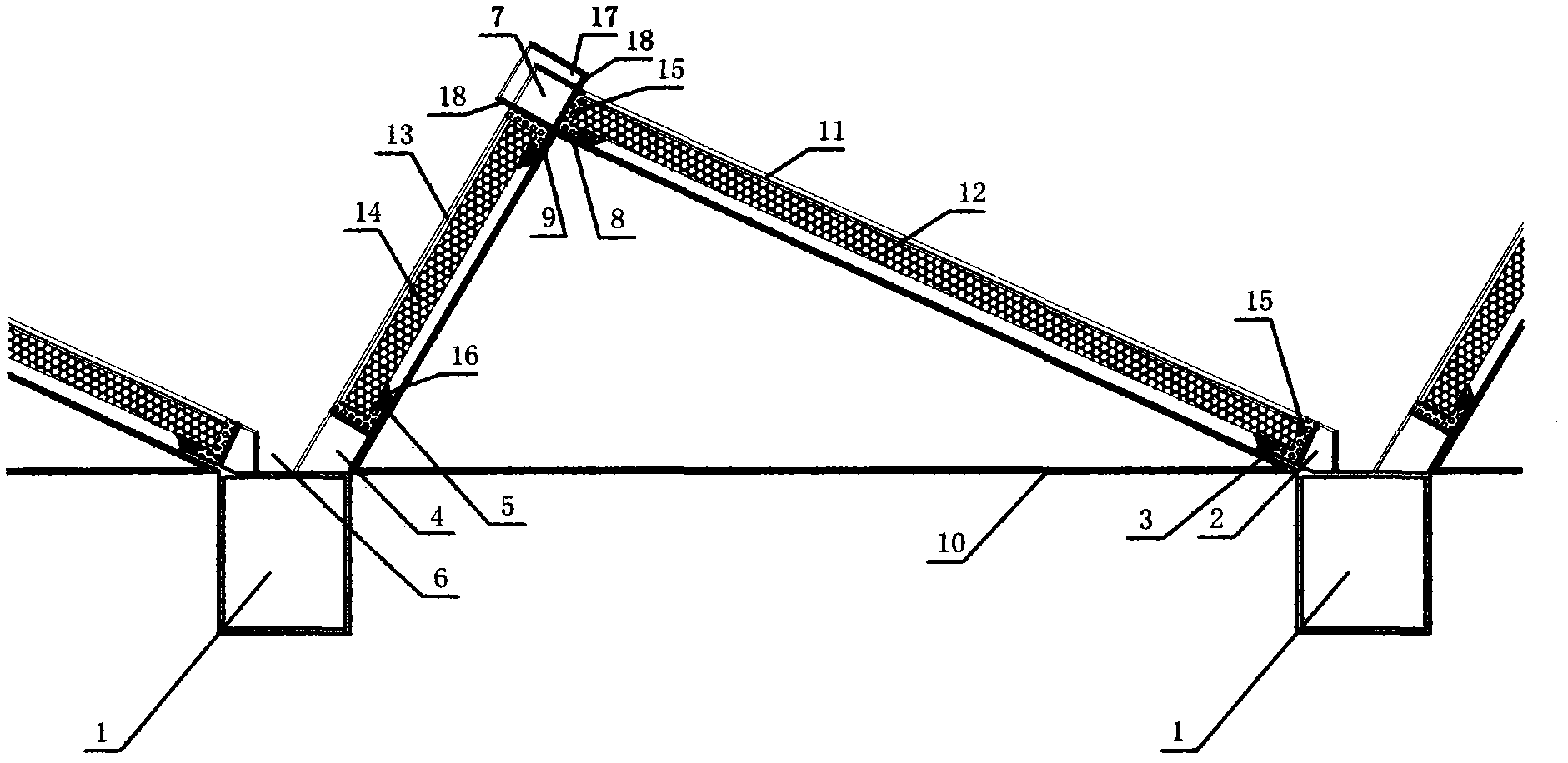
[0022] The cross-sectional structure diagram of the roof photoelectric conversion building combined with triangular thermal insulation reflective panels and solar thermal insulation panels is as follows figure 1 As shown, wherein: 1 is the aluminum alloy lower beam, 2 is the aluminum alloy lower beam solar panel support plate, 3 is the solar panel lower support plate, 4 is the thermal insulation reflective plate support plate, 5 is the thermal insulation reflective plate lower support plate, 6 is the drainage channel, 7 is the aluminum alloy upper beam, 8 is the aluminum alloy upper beam solar panel support plate, 9 is the aluminum alloy upper beam thermal insulation reflector plate, 10 is the triangular bracket, 11 is the solar panel, and 12 is the solar energy The insulation board under the battery board, 13 is a reflector or a light-concentrating board, 14 is a heat preservation board under the reflector, 15 is a sealant, 16 is a damping gasket, 17 is an air duct, and 18 is ...

Embodiment 2

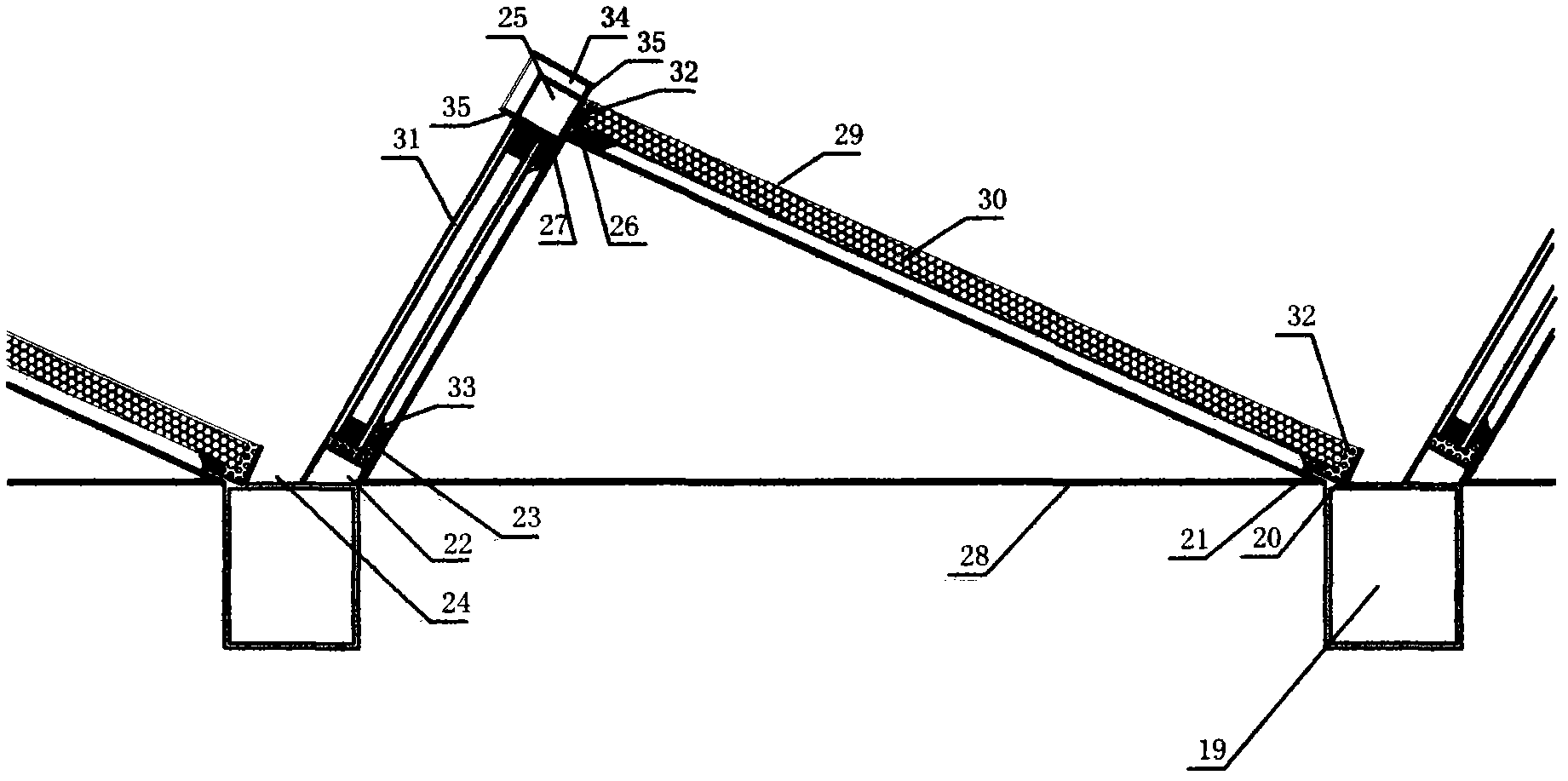
[0025] The cross-sectional structure diagram of the roof photoelectric conversion building composed of triangular light-transmitting hollow glass and solar thermal insulation panels is as follows figure 2 As shown, wherein: 19 is an aluminum alloy lower beam, 20 is an aluminum alloy lower beam solar panel support plate, 21 is a solar panel lower support plate, 22 is a transparent hollow glass support plate, and 23 is a transparent hollow glass lower support plate Plate, 24 is a drainage channel, 25 is an aluminum alloy upper beam, 26 is an aluminum alloy upper beam solar panel supporting plate, 27 is an aluminum alloy upper beam transparent hollow glass supporting plate, 28 is a triangular bracket, and 29 is a solar panel. 30 is a heat insulation board under the solar panel, 31 is a light-transmitting hollow glass, 32 is a sealant, 33 is a damping gasket, 34 is an air duct, and 35 is an air outlet of the air duct.

[0026] During assembly, the two ends of the aluminum alloy l...

Embodiment 3

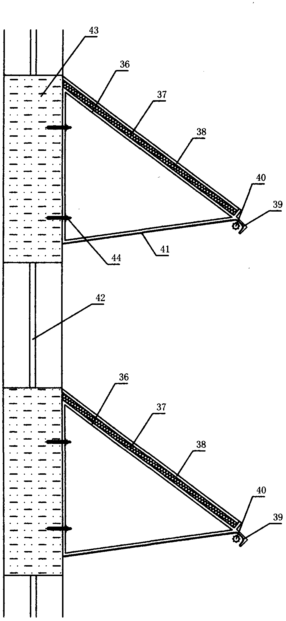
[0028] The cross-sectional structure diagram of the building with triangular reflectors and solar thermal insulation panels combined wall or curtain wall photoelectric conversion image 3As shown, wherein: 36 is a triangular bracket, 37 is a solar panel insulation board, 38 is a solar panel, 39 is a reflector for a lighting lamp, 40 is a lighting lamp, 41 is a reflector or a concentrating board, and 42 is a light-transmitting building glass Or light-transmitting building doors and windows, 43 is a body of wall or a curtain wall, and 44 is a connecting bolt.

[0029] During assembly, triangular support 36 is fixed on the body of wall 43 with connecting bolt 44, and solar cell panel insulation board 37 is installed on the lower floor of the outer slope of triangular support 36, and solar cell panel 38 is installed on the solar cell panel insulation board 37, and in the light reflector 39 Lighting lamp 40 is installed, and reflector or light-gathering plate 41 is installed on the...


PUM


Abstract

The invention relates to a building with triangular solar photovoltaic conversion structures, which comprises a solar controller, a storage battery, an inverter, solar panels, transparent building glass, triangular supporting structures and heat insulating materials, wherein the back surfaces of the triangular supporting structures are connected onto a building elevation structure, the solar panels for photovoltaic conversion are installed on the inclined surfaces of the triangular supporting structures, light reflecting plates, arc-shaped light condensing plates, decoration plates or decoration glass plates are installed on the other surfaces of the triangular supporting structures, and the right-angle outward extension surfaces of the triangular supporting structures are the transparent building glass or transparent building doors / windows.

Description

technology field; [0001] The invention relates to solar photoelectric conversion buildings, including roofs, walls and curtain walls. Background technique; [0002] The current building-integrated photovoltaics is more about moving the installation method of the inclined plane structure of the ground power station directly to the roof or the wall, which not only brings hidden dangers to building safety, but also the stability of the photovoltaic system itself. Destroy the overall beauty of the building to a certain extent. Due to the opaqueness of the photovoltaic system, the two functions of power generation and daylighting cannot be realized. Since the solar panel is a single-layer structure and does not have the function of heat preservation, it is impossible to achieve building energy saving. [0003] There is no wind dust or snow removal device on the solar panel of the existing solar power generation device, because the light-transmitting outer panel has been impacte...

Claims


Application Information

Patent Timeline
IPC IPC(8): E04H1/00E04D13/18E04D13/04E04B1/80H01L31/042H02S20/22H02S40/42
CPCF24S25/10Y02B10/10Y02B10/20Y02E10/47Y02E10/50
Inventor 王广武
Owner 王广武
Learn More