Grinding cushion, and grinding device and grinding method using grinding cushion
A grinding method and a technology of a grinding device, which are applied in the direction of grinding tools, etc., can solve the problems of increasing production costs, uneven grinding of the central area and edge area of the wafer, etc., and achieve the effect of improving uniformity and improving production yield
- Summary
- Abstract
- Description
- Claims
- Application Information
AI Technical Summary
Problems solved by technology
Method used
Image

Examples
Embodiment approach
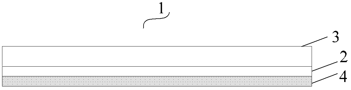
[0045] In order to solve the above-mentioned technical problem, the present invention provides a kind of lapping pad that can grind wafer edge separately, according to one embodiment of the present invention, this lapping pad comprises:
[0046] The first grinding area is arranged on the edge of the grinding pad and is used for grinding the edge of the wafer;
[0047] a second grinding area, the second grinding area can accommodate at least the entire wafer, and is used for grinding the entire wafer surface;
[0048] Wherein, there is a groove between the first grinding area and the second grinding area of the grinding pad.
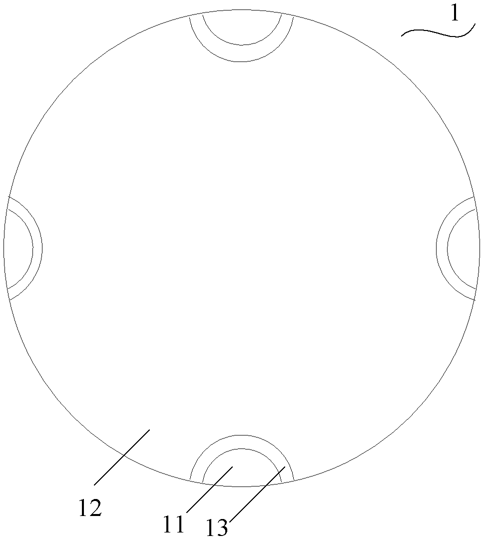
[0049] figure 2It is a top view of a polishing pad according to an embodiment of the present invention. As shown in the figure, a plurality of first grinding areas 11 are arranged on the grinding pad 1, and the first grinding areas 11 are arranged at intervals on the edge of the grinding pad 1 and surround the second grinding area 12 of the grinding ...
Embodiment approach 2
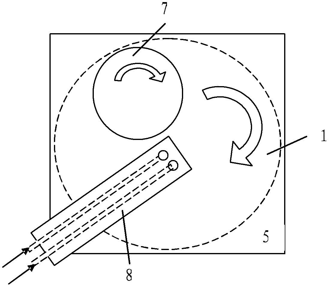
[0061] According to another embodiment of the present invention, the present invention provides a grinding device including the above-mentioned grinding pad, and the grinding device further includes a first conveying device. The grinding pad is arranged on the grinding table, and the grinding pad includes a first grinding area for grinding the edge of the wafer, and a second grinding area for grinding the entire wafer surface; the first grinding area of the grinding pad There is a groove between the second grinding area. The groove is used to isolate the grinding liquid from entering the second grinding area when grinding the edge of the wafer. In addition, the first grinding area, the second grinding area and the groove jointly form a shape of a grinding pad and correspond to a shape of the grinding table.
[0062] refer to Figure 7 , Figure 7 It is a cross-sectional view of a grinding device grinding a wafer according to an embodiment of the present invention. This g...
Embodiment approach 3
[0070] The grinding method of the present invention, which uses the above-mentioned grinding device to independently grind the edge of the wafer, will be described in detail below in conjunction with the accompanying drawings.
[0071] According to still another embodiment of the present invention, there is provided a polishing method using the polishing apparatus described above. Figure 9 It is a schematic flow chart of a grinding method using the above-mentioned grinding device according to an embodiment of the present invention. The grinding method includes:
[0072] Step S1, providing a grinding pad to be placed on the rotatable grinding table, the grinding pad includes a first grinding area and a second grinding area, and a groove is formed between the first grinding area and the second grinding area;
[0073] Step S2, providing a wafer, and loading the wafer on the grinding head;
[0074] Step S3, providing a first conveying device placed above the polishing pad, the ...
PUM
| Property | Measurement | Unit |
|---|---|---|
| Diameter | aaaaa | aaaaa |
Abstract
Description
Claims
Application Information
 - R&D
- Intellectual Property
- Life Sciences
- Materials
- Tech Scout
- Unparalleled Data Quality
- Higher Quality Content
- 60% Fewer Hallucinations
Browse by: Latest US Patents, China's latest patents, Technical Efficacy Thesaurus, Application Domain, Technology Topic, Popular Technical Reports.
© 2025 PatSnap. All rights reserved.Legal|Privacy policy|Modern Slavery Act Transparency Statement|Sitemap|About US| Contact US: help@patsnap.com