Electron beam control system and method for electronic gun

A technology of electron beam current and control method, which is applied in the direction of circuits, discharge tubes, electrical components, etc., to achieve the effects of suppressing discharge, reducing electron beam current, and suppressing ripples

Active Publication Date: 2013-06-26
GUILIN THD TECH CO LTD
View PDF4 Cites 7 Cited by
  • Summary
  • Abstract
  • Description
  • Claims
  • Application Information

AI Technical Summary

Problems solved by technology

In this way, for applications that require high precision, such as precision electron beam welding, the limitations of conventional electron beam current control methods are undoubtedly revealed

Method used


Image

  • Electron beam control system and method for electronic gun
  • Electron beam control system and method for electronic gun
  • Electron beam control system and method for electronic gun

Examples


Embodiment Construction

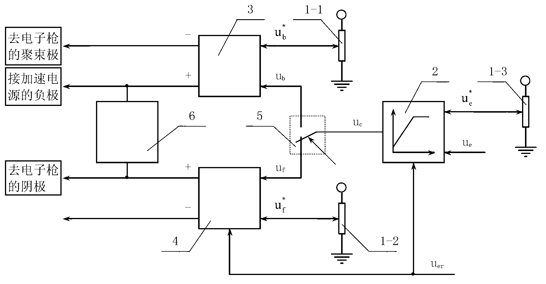
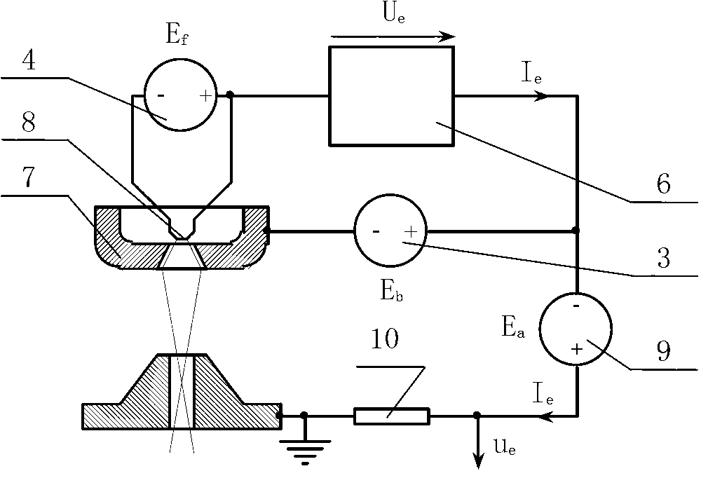
[0024] An electron beam current control system for an electron gun is mainly composed of a grid bias power supply unit 3 , a cathode power supply unit 4 , an electron beam current regulator 2 , a signal gating switch 5 , a self-stabilizing current device 6 , and a central control unit 1 . figure 1 The principle schematic diagram of the principle schematic diagram of the electron beam current control system of the electron gun of the present invention is given. figure 2 A schematic diagram of the connection between the power supply of the electron beam generating system of the electron gun, the self-stabilizing device 6 and the electron gun is given.

[0025] The central control unit 1 includes a grid bias power supply unit setting signal generator 1-1, a cathode power supply unit setting signal generator 1-2, and an electron beam current setting signal generator 1-3. Among them, the grid bias power supply unit setting signal generator 1-1 generates the voltage preset signal o...


PUM


Abstract

The invention discloses electron beam control system and method for an electronic gun. An additional self-current-stabilizing device comprises passive elements such as a resistor or inductor. The self-current-stabilizing device (6) is serially connected to an electron beam circuit. One end of the self-current-stabilizing device is connected to a positive output electrode of a gate-bias power supply unit (3). The other end of the self-current-stabilizing device is connected to a positive output electrode of a bombardment power supply of an indirect-heating electron gun or an optional output electrode of a filament power supply of the indirect-heating electron gun. Constant voltage Ue relative to an electron beam and generated by the indirect-heating electron gun is directly superposed to gate-bias voltage to form local non-delay negative feedback, and current stabilization is achieved.

Description

technical field [0001] The invention relates to electron beam processing equipment, in particular to an electron gun electron beam current control system and method thereof. Background technique [0002] There are two types of cathodes for electron guns that emit electron beams: direct heating and indirect heating. The working state of the cathode emitting electron beam has a temperature-limited state and a space-charge-limited state. The saturated electron beam current density emitted by the cathode in the temperature-limited state is given by the formula decision, where i s is the saturated electron beam current density emitted by the cathode, A 0 is the Richardson constant, T is the thermodynamic temperature of the cathode, k is the Boltzmann constant, is the work function of the cathode material. In the state of space charge limitation, at a certain cathode temperature, the electron beam current density emitted by the cathode is given by the formula decision, wh...

Claims


Application Information

Patent Timeline
Patent Type & Authority Applications(China)
IPC IPC(8): H01J37/24
Inventor 韦寿祺黄小东陆思恒郭华艳王伟蒋思远陆苇黄海黄地送
Owner GUILIN THD TECH CO LTD
Why Eureka
Try Eureka