Ripple wave inhibition method and circuit and load driving circuit using ripple wave inhibition circuit

A ripple suppression and load current technology, applied in the field of power electronics, can solve the problems of high power consumption of transistors and high requirements on heat dissipation performance of transistors, and achieve the effects of low power consumption, ripple suppression, and flicker avoidance.

Active Publication Date: 2016-11-23
SILERGY SEMICON TECH (HANGZHOU) CO LTD
View PDF4 Cites 7 Cited by
  • Summary
  • Abstract
  • Description
  • Claims
  • Application Information

AI Technical Summary

Problems solved by technology

[0005] However, the above-mentioned way of using the drain voltage of the transistor to follow the change of the output voltage ripple to suppress the ripple of the LED driving current consumes a lot of energy in the transistor, and also requires high requirements on the heat dissipation performance of the transistor. Larger size package to ensure the thermal performance of the transistor

Method used


Image

  • Ripple wave inhibition method and circuit and load driving circuit using ripple wave inhibition circuit
  • Ripple wave inhibition method and circuit and load driving circuit using ripple wave inhibition circuit
  • Ripple wave inhibition method and circuit and load driving circuit using ripple wave inhibition circuit

Examples


Embodiment Construction

[0071] Several preferred embodiments of the present invention will be described in detail below with reference to the accompanying drawings, but the present invention is not limited to these embodiments. The present invention covers any alternatives, modifications, equivalent methods and schemes made on the spirit and scope of the present invention. In order to provide the public with a thorough understanding of the present invention, specific details are set forth in the following preferred embodiments of the present invention, but those skilled in the art can fully understand the present invention without the description of these details.

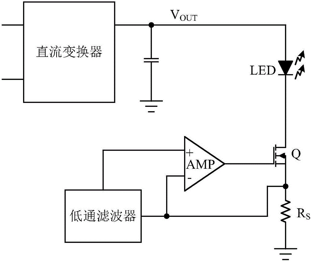
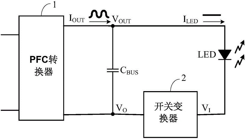
[0072] The present application provides a ripple suppression method to suppress the ripple on the load when the ripple signal output by the signal source supplies power to the load, so that the current signal flowing through the load maintains a constant flow. Wherein, in all the embodiments of the present application, the load is an LED ...


PUM


Abstract

The invention provides a ripple wave inhibition method and circuit and a load driving circuit using the ripple wave inhibition circuit. A switching converter is used for buffering output energy of a preceding stage signal source, so that voltage difference between input voltage signals and output voltage signals of the switching converter changes following ripple wave signals output by the signal source, ripple waves on a load are inhibited, the load current signals are kept to be a direct current value, it is avoided that the load like an LED lamp flicks as ripple wave components exist in the load current signals, and as the average value of the voltage difference between input voltage signals and output voltage signals of the switching converter is zero, the switching converter does not additionally consume energy output by the preceding stage signal source. Therefore, the load driving circuit with the ripple wave inhibition circuit is low in power consumption.

Description

technical field [0001] The invention relates to power electronics technology, in particular to a ripple suppression method, a circuit and a load driving circuit using the same. Background technique [0002] The output of the switching power supply for driving the LED load usually contains ripples, wherein there will be power frequency or lower frequency ripples in the output current, and at the same time, the output voltage will also have ripples. If such a switching power supply is used to directly drive the LED load, it will inevitably cause the LED light to flicker or strobe. [0003] In the traditional switching power supply, a large electrolytic capacitor is used to store energy and provide DC voltage for the subsequent LED load, so that the output current ripple of the driving power supply is very low. However, power factor correction cannot be provided in this way, and the use of electrolytic capacitors will also affect the life of the circuit. [0004] In order to ...

Claims


Application Information

Patent Timeline
Patent Type & Authority Applications(China)
IPC IPC(8): H02M1/15H05B33/08H05B44/00
CPCH02M1/15H05B45/37H02M7/04G05F1/56H02M1/14H05B45/3725H05B45/375H05B45/385H05B45/38H05B45/44
Inventor 黄秋凯邓建
Owner SILERGY SEMICON TECH (HANGZHOU) CO LTD
Why Eureka
Try Eureka