Buck converter with single stage

Active Publication Date: 2014-04-17
IND TECH RES INST
View PDF1 Cites 7 Cited by
  • Summary
  • Abstract
  • Description
  • Claims
  • Application Information

AI Technical Summary

Benefits of technology

The present patent offers a single-stage buck converter circuit that includes a buck device, a semiconductor component, a first resonant circuit, and a second resonant circuit. The first resonant circuit helps adjust the actuation time constant, while the second resonant circuit helps suppress ripple. The technical effect of such a circuit is to improve the efficiency and stability of the buck converter circuit.

Problems solved by technology

However, the capacitor with large capacitance value is required to use electrolytic capacitor, which is susceptible to the switch and the temperature such external environment factors causing its short service life and thus shorten the service life of capacitor.

Method used


Image

  • Buck converter with single stage
  • Buck converter with single stage
  • Buck converter with single stage

Examples


Embodiment Construction

[0016]For your esteemed members of reviewing committee to further understand and recognize the fulfilled functions and structural characteristics of the disclosure, several exemplary embodiments cooperating with detailed description are presented as the follows.

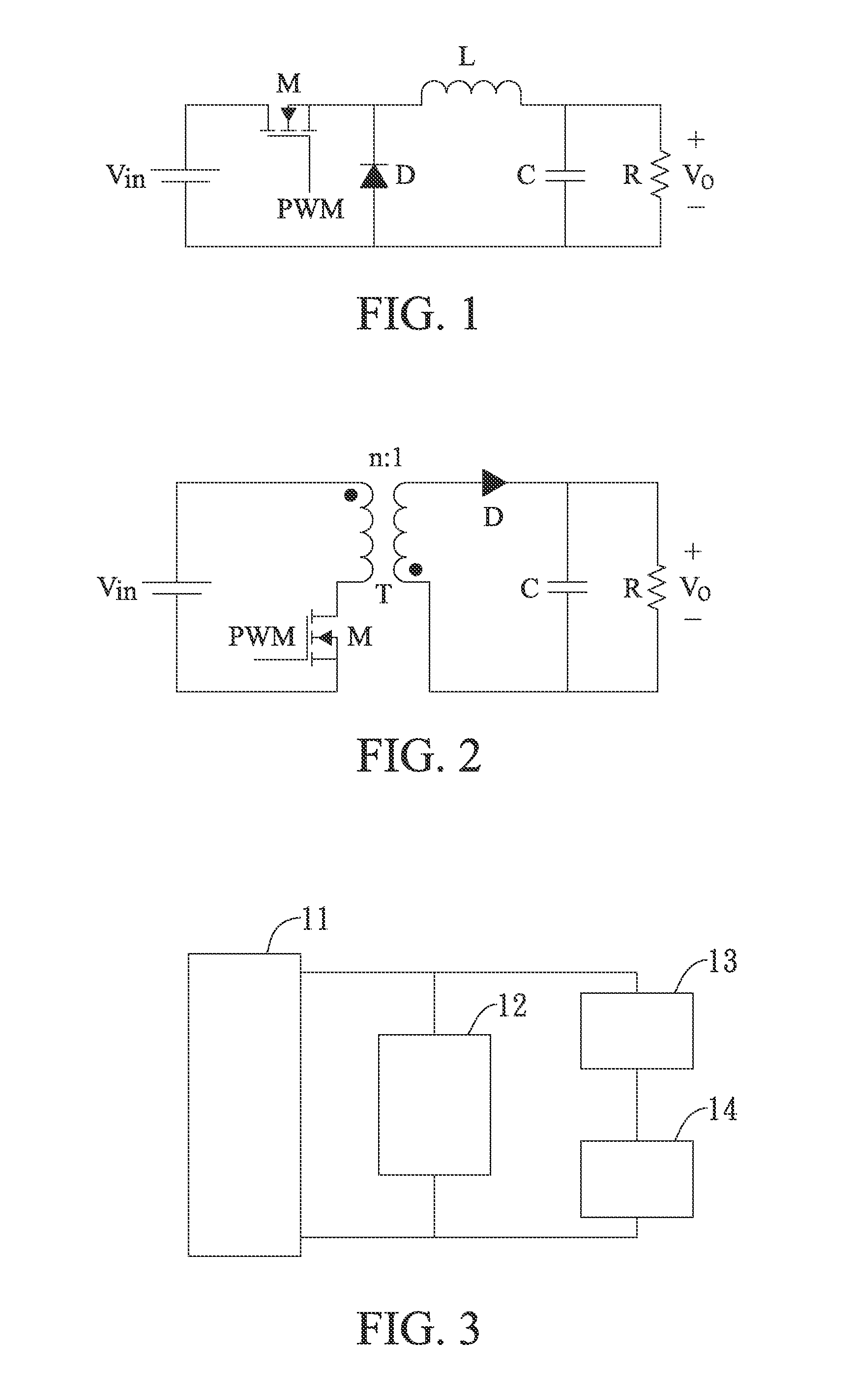
[0017]FIG. 3 is an embodiment of the single-stage buck converter according to the present disclosure. The single-stage buck converter includes: a buck device 11, a semiconductor component 12, a first resonant circuit 13 and a second resonant circuit 14. The semiconductor component 12 can be a diode, which is used to adjust the output power and output voltage. The first resonant circuit 13 is coupled to the semiconductor element 12, used to adjust the actuation time constant. The second resonant circuit 14 is coupled to the first resonant circuit 13, used to suppress the ripple. And the buck device 11 can also be a buck converter.

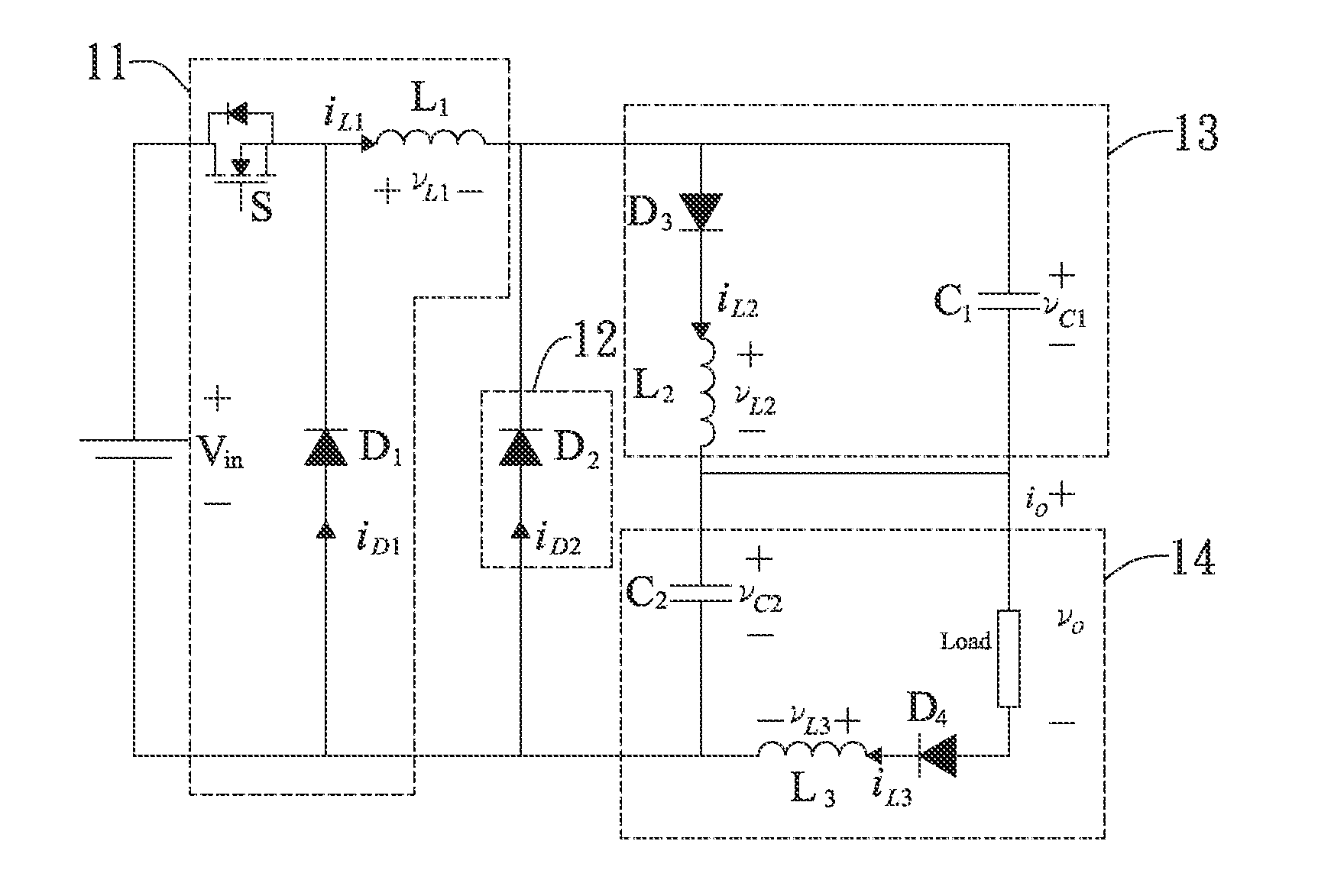
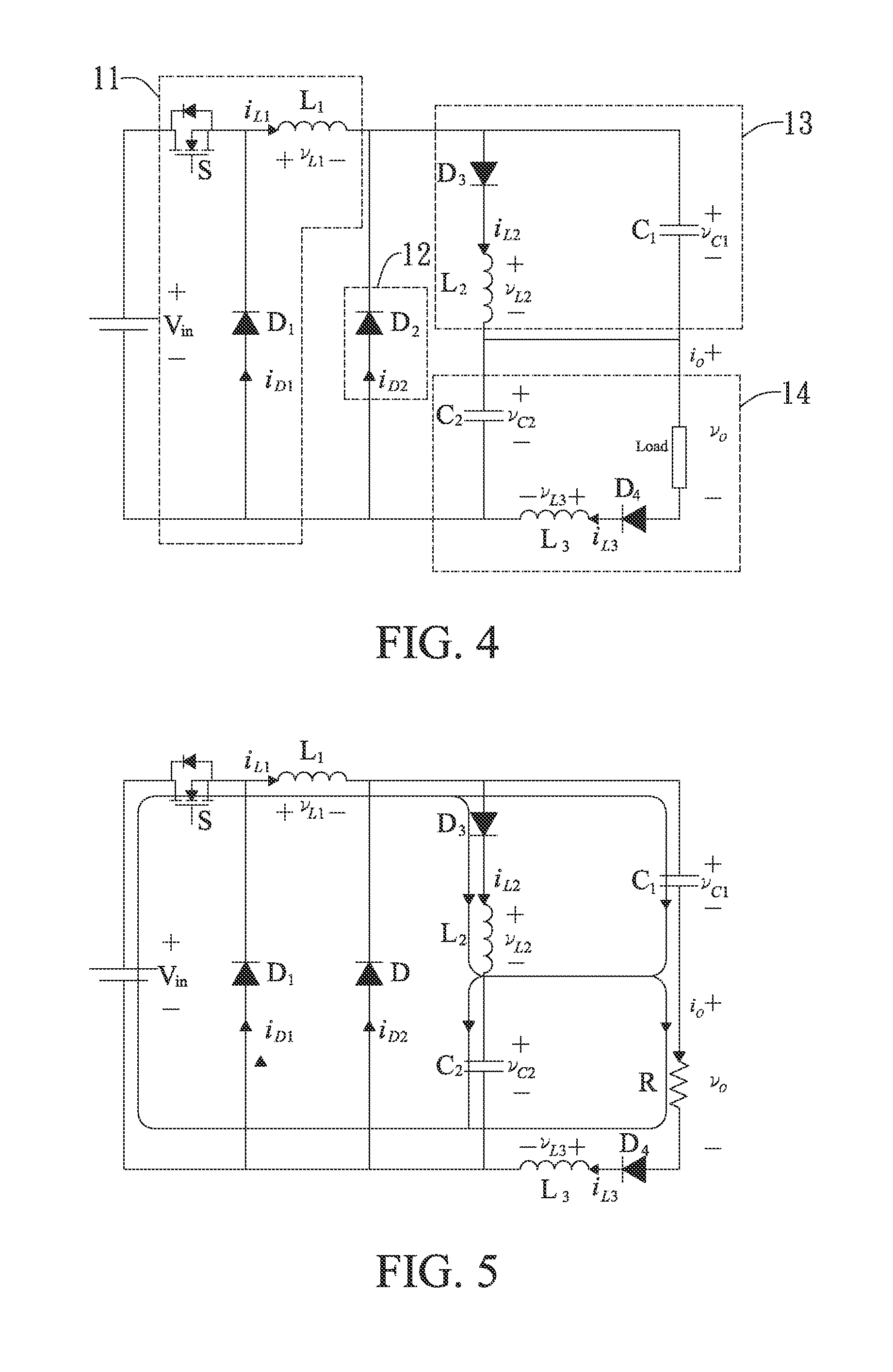
[0018]FIG. 4 shows the present disclosure application example. In this example, the buck device 11...


PUM


Abstract

The present disclosure provides a mirror device with illumination comprising a transparent conductive substrate, an isolation layer, a mirror layer and a light emitting diode (LED) layer. The isolation layer, formed on a surface of the transparent conductive substrate, divides the surface of the transparent conductive substrate into at least one first region and at least one second region. The mirror layer formed on the transparent conductive substrate within the at least one first region, while the LED layer is formed on the transparent conductive substrate within the at least one second region, wherein the mirror layer and the LED layer are electrically isolated from each other. In another embodiment, the present disclosure further provides a mirror box having the mirror device with illumination disposed therein so that the mirror device can be easily carried and kept in the pocket, or purse of user.

Description

CROSS REFERENCE TO RELATED APPLICATION[0001]The present application is based on, and claims priority from, Taiwan (International) Application Serial Number 101137736, filed on Oct. 12, 2012, the disclosure of which is hereby incorporated by reference herein in its entirety.TECHNICAL FIELD[0002]The present disclosure is a buck converter with single-stage, and more particularly, to a buck converter with single-stage, which has an input rapid response, low-ripple output current and longer circuit useful life.TECHNICAL BACKGROUND[0003]Because inductance value of inductor being an energy storage component in the buck converter will affect input current response speed and output current ripple, the input current response speed is faster and the output current ripple is relatively larger if the inductance value of inductor being an energy storage component is smaller; otherwise, the buck converter input current response speed is slower and the output current ripple is smaller if the induct...

Claims


Application Information

Patent Timeline
IPC IPC(8): H02M1/14
CPCH02M1/14H02M3/155H02M3/158
Inventor CHEN, PO-YENPAN, CHING-TSAI
Owner IND TECH RES INST
Why Eureka
Try Eureka