
Motor and concrete vibrating rod using same

A motor and vibrator technology, which is applied in the direction of electric components, electromechanical devices, electrical components, etc., can solve the problems of poor impact resistance of electronic components, can only be installed outside, and high cost, so as to improve work performance and ensure normal work. , the effect of strong excitation force

Inactive Publication Date: 2013-06-19
冯玉加
View PDF10 Cites 7 Cited by
  • Summary
  • Abstract
  • Description
  • Claims
  • Application Information

AI Technical Summary

Problems solved by technology

Although it solves the above-mentioned defects in ordinary DC motors, because the work of brushless DC motors requires the cooperation of a dedicated brushless DC motor controller and a Hall element that detects the rotational position of the motor, due to the limitations of the rod space and the environment The brushless DC motor controller can only be set outside and connected to the brushless DC motor through cables, while the Hall element must be installed in the rod body and connected to the external brushless DC motor controller. This structure of the entire device is also Consists of two parts (rod body and BLDC motor controller), resulting in similar drawbacks to solutions using AC motors, except that the BLDC motor controller is relatively smaller
On the other hand, large changes in power during construction cause large changes in motor current, and the electronic components of electronic frequency conversion control equipment have relatively poor impact resistance; moreover, Hall elements are relatively fragile and are easily damaged in complex and harsh construction environments. And because the rod body is in a sealed state, the high temperature formed by the operation of the motor will greatly reduce the working life of the Hall element, and even cause damage to it.
At the same time, its cost is relatively high
Based on the above reasons, the vibrating rod adopting this technical scheme has poor practicability, and the actual use value is not high
[0008] To sum up, it can be seen that due to the limitation of the size of the rod body, the space inside the rod body is limited. In the case of no external equipment, it is difficult for the existing related technologies to directly implant the ordinary motor into the vibrator rod body to achieve relevant technical indicators.

Method used


Image

  • Motor and concrete vibrating rod using same
  • Motor and concrete vibrating rod using same
  • Motor and concrete vibrating rod using same

Examples


Embodiment Construction

[0047] In order to make it easier for those skilled in the art to further understand the present invention, and to clearly understand the technical solutions described in this application, and to fully and fully disclose the relevant technical content of the present invention, the specific embodiments of the present invention will be described in detail below in conjunction with the accompanying drawings Description, obviously, the described specific implementation is only an example to give a part of the embodiments of the present invention, to help understand the present invention and its core idea. Based on the embodiments of the present invention, all other embodiments obtained by persons of ordinary skill in the art without creative work, and / or without departing from the spirit and essence of the present invention, even if made according to the present invention Various corresponding changes and modifications, but these corresponding changes and modifications should fall ...


PUM


Abstract

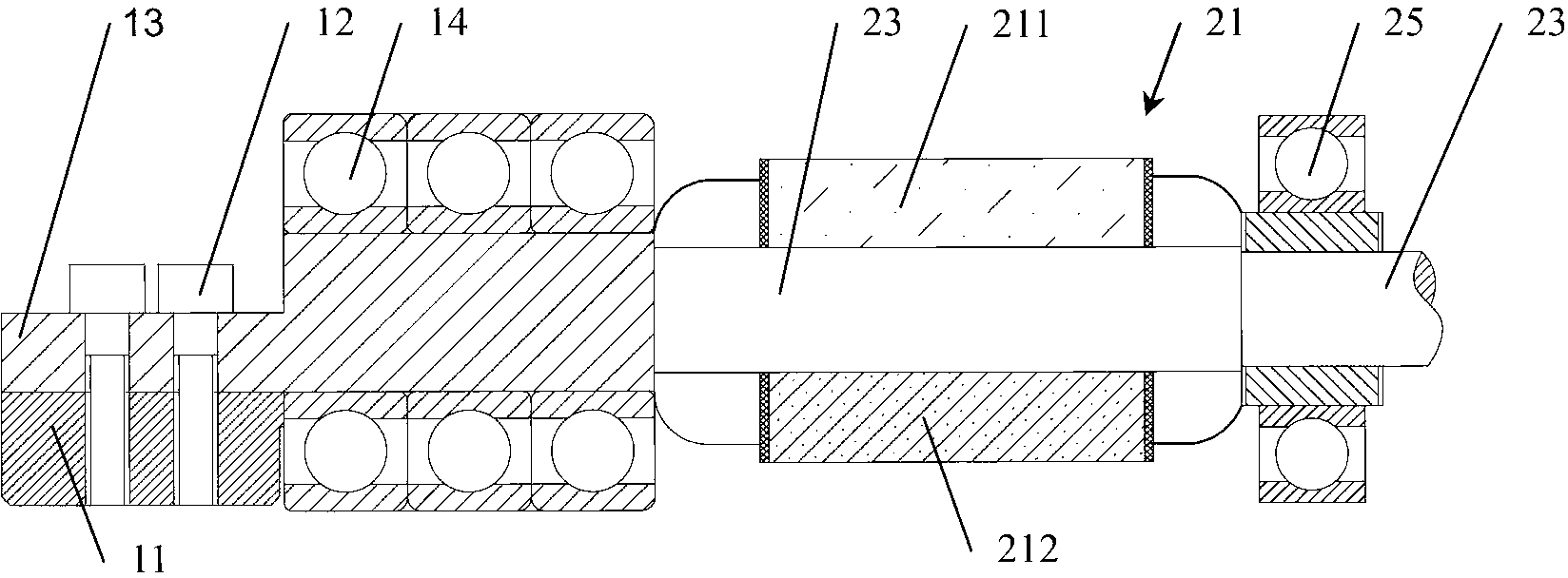
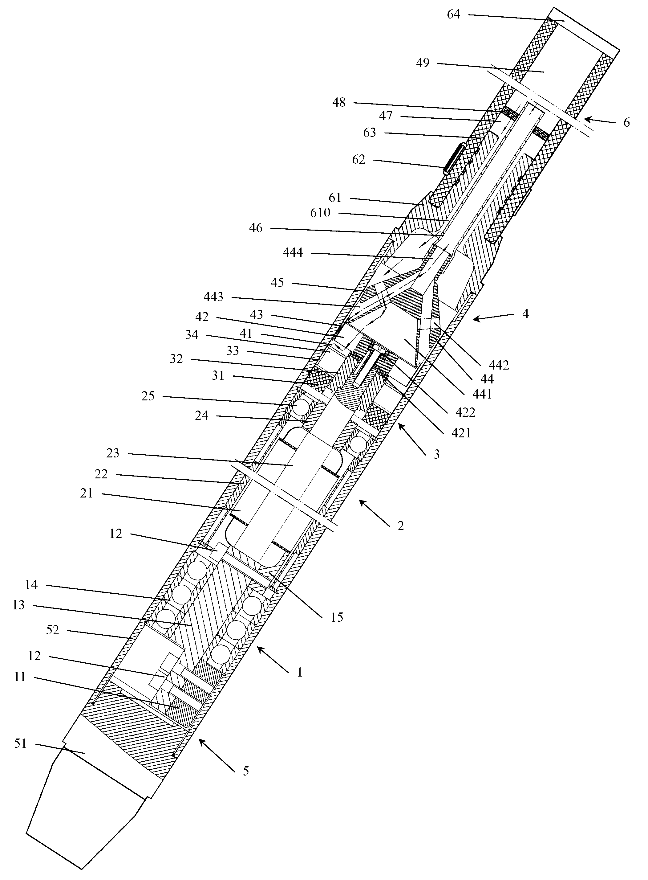
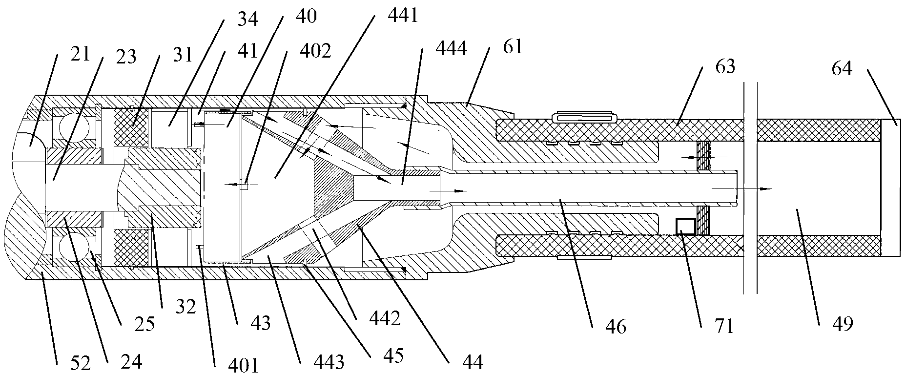
The invention discloses a motor and a concrete vibrating rod using the same. The brush motor comprises a stator, a rotating shaft and a rotor fixed on the rotating shaft, wherein the rotating shaft is supported by a bearing; a commutator assembly and a corresponding electric brush assembly are arranged on the rotating shaft; the rear end of the motor supports the first bearing of the rotating shaft between the rotor and the commutator assembly to partition the rotor, the commutator assembly and the electric brush assembly in two difference spaces, so that the commutator assembly and the electric brush assembly are positioned in a space outside the first bearing. The invention also discloses a method for improving the working performance of the brush motor and the concrete vibrating rod using the brush motor. The space outside the first bearing is communicated with a pipeline-type cavity in a tail pipe system. The related technical indexes of the vibrating rod can be effectively met without any external equipment.

Description

technical field [0001] The invention relates to a concrete internal vibrator, in particular to a motor built-in concrete vibrator; and also relates to a motor. Background technique [0002] Concrete vibrating rods (hereinafter referred to as vibrating rods), also known as concrete vibrating rods, concrete internal vibrators, plug-in concrete vibrators, etc., insert the rod body of the vibrating rod into the concrete when working, and direct its vibration waves Pass it to concrete to remove the air bubbles in the concrete pouring and construction, and perform tamping to make the concrete compact and eliminate the honeycomb and pockmarks of the concrete, so as to improve its strength and ensure the quality of concrete components. In order to effectively achieve the above purpose, according to the relevant technical specifications, the vibration frequency of the concrete vibrator is required to be above 167Hz, which belongs to the high-frequency vibrator. If the vibration power...

Claims


Application Information

Patent Timeline
IPC IPC(8): H02K23/66H02K9/28E04G21/08
Inventor 冯玉加
Owner 冯玉加
Learn More