Low dielectric glass and fiber glass

A fiber and glass technology, used in printed circuits, electrical components, circuit substrate materials, etc., can solve the problem of high fiber molding temperature

Inactive Publication Date: 2013-06-12
PPG IND OHIO INC
View PDF13 Cites 7 Cited by
  • Summary
  • Abstract
  • Description
  • Claims
  • Application Information

AI Technical Summary

Problems solved by technology

Although these boron-free glasses offer low D k , have presumably relatively low raw material costs, bu...

Method used


Image

  • Low dielectric glass and fiber glass
  • Low dielectric glass and fiber glass
  • Low dielectric glass and fiber glass

Examples


Embodiment Construction

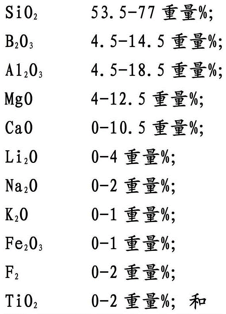
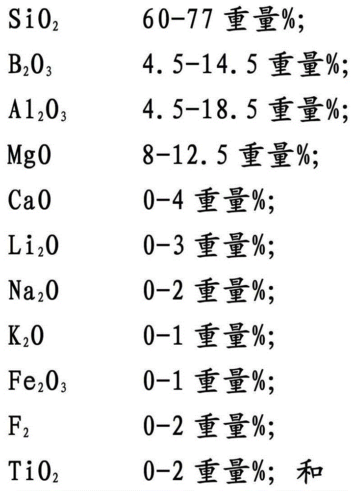
[0065] In order to reduce D k and D f , including SiO with low electric susceptibility in the composition of the present invention 2 and B 2 o 3 is useful. Although B 2 o 3 itself will melt at low temperature (350°C), but it is unstable to moisture attack in ambient air, so pure B 2 o 3 fibers cannot be practically used in PCB laminates. SiO 2 and B 2 o 3 Both are network formers, and mixtures of the two will produce significantly higher fiber forming temperatures than E-glass, as well as D-glass. In order to reduce the fiber forming temperature, MgO and Al can be included 2 o 3 , to replace some SiO 2 . Calcium oxide (CaO) and SrO can also be used in combination with MgO, but they are not as desirable as MgO since both have higher polarizability than MgO.

[0066] In order to reduce the batch cost, the B 2 o 3 Use at lower concentrations than in D-glass. However, including enough B 2 o 3 to prevent phase separation in the glass melt, thereby providing bet...


PUM

PropertyMeasurementUnit
Young's modulusaaaaaaaaaa
Microhardnessaaaaaaaaaa
Young's modulusaaaaaaaaaa

Abstract

Glass compositions are provided that are useful in a variety of applications including, for example, electronics applications, reinforcement applications, and others. Some embodiments of glass compositions can provide desirable dielectric constants, desirable dissipation factors, and/or desirable mechanical properties while also having desirable fiber forming properties.

Description

[0001] Cross-Referenced Related Applications [0002] This application claims priority to U.S. Patent Application No. 13 / 229012, filed September 9, 2011, which is a continuation-in-part of U.S. Patent Application No. 12 / 940764, filed November 5, 2010 , Application No.12 / 940764 is a continuation application of U.S. Patent Application No.11 / 610761 filed on December 14, 2006, and the current U.S. Patent No.7829490 (issued on November 9, 2010), the content of which is This is incorporated by reference in its entirety. Background of the invention [0003] The present invention relates to glass compositions which may be used, for example, to form glass fibers. Such glass fibers can be used in a wide variety of end applications. [0004] For example, in some embodiments, glass fibers are used to form fibers that can be used to reinforce composite substrates including printed circuit boards ("PCBs"). More specifically, some embodiments of the present invention relate to glass fiber...

Claims


Application Information

Patent Timeline
IPC IPC(8): C03C3/093C03C3/118H05K1/03
CPCC03C3/091C03C3/093C03C3/118C03C13/00H05K1/0366H05K1/03
Inventor 李洪C·A·理查德斯
Owner PPG IND OHIO INC
Why Eureka
Try Eureka