display panel

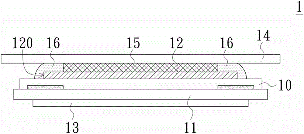
A display panel and display area technology, which is applied in nonlinear optics, instruments, optics, etc., can solve the problems of colloid 15 overflowing, damage, and bonding failure of covering substrate 14, so as to achieve increased stability, prevent glue overflowing, and adhesion sex increasing effect

Inactive Publication Date: 2015-09-30
AU OPTRONICS CORP
View PDF3 Cites 0 Cited by
  • Summary
  • Abstract
  • Description
  • Claims
  • Application Information

AI Technical Summary

Problems solved by technology

However, because the size of the polarizer 12 is insufficient, the frame glue 16 will straddle the side surface 120 of the polarizer 12 during the coating process, and cannot be completely coated on the polarizer 12, and the strength of the frame glue 16 is insufficient to be effective. The force of blocking the outward flow of the colloid 15 will cause the colloid 15 to overflow the glue, which will eventually lead to the failure of bonding the covering substrate 14, and may even cause the colloid 15 to flow into the liquid crystal display device and cause damage

Method used


Image

  • display panel
  • display panel
  • display panel

Examples


Embodiment Construction

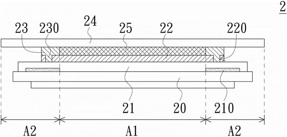
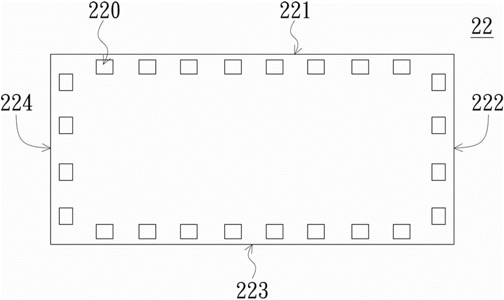
[0053] Please refer to figure 2 , figure 2 It is a schematic cross-sectional view of a display panel according to an embodiment of the present invention. The display panel 2 is, for example, a liquid crystal display panel or a self-luminous display panel. Such as figure 2 As shown, the display panel 2 described in this embodiment includes a first substrate 20 , a second substrate 21 , a polarizer 22 and a sealant 23 . The first substrate 20 is disposed relative to the second substrate 21 , the first substrate 20 is, for example, a thin film transistor array substrate, and the second substrate 21 is, for example, a color filter substrate, but the present invention is not limited thereto. The polarizer 22 has a plurality of holes 220 , and the second substrate 21 is located between the first substrate 20 and the polarizer 22 . The frame glue 23 is disposed on the polarizer 22, and the frame glue 23 has a plurality of protrusions 230 corresponding to the holes 220 of the p...


PUM


Abstract

A display panel comprises a first substrate, a second substrate, a Polaroid and a glue frame. The first substrate is opposite to the second substrate which is between the first substrate and the Polaroid. The Polaroid is provided with a plurality of holes and the glue frame is disposed on the Polaroid. The glue frame is provided with a plurality of projections corresponding to the holes and disposed in the holes respectively. According to the invention, the stability of the glue frame on the Polaroid is improved in a cover substrate fit process because the projections of the glue frame are disposed in the holes of the Polaroid and the glue frame will not collapse because of press during fit of cover substrates. The adhesiveness of the glue frame is increased, so that glue between the cover substrates and the Polaroid can be limited in the glue frame effectively and glue overflow is prevented.

Description

technical field [0001] The present invention relates to a display panel, and in particular to a display panel with a frame glue adhesion enhancing structure. Background technique [0002] With the advent of the digital age, the technology of display devices has grown rapidly and has become an indispensable electronic product, so the technical and functional requirements for display devices are also getting higher and higher. Among them, liquid crystal display devices are popular among high-end products because of their high brightness and large viewing angle. [0003] A liquid crystal display device mainly includes a liquid crystal display panel and a backlight module. Among them, the main structure of the liquid crystal display panel is as follows: figure 1 As shown, the liquid crystal display panel 1 includes a color filter substrate 10 , a thin film transistor array substrate 11 , polarizers 12 , 13 , a cover substrate 14 and the like. Such as figure 1 As shown, the c...

Claims


Application Information

Patent Timeline
Patent Type & Authority Patents(China)
IPC IPC(8): G02F1/1339G02F1/1335
Inventor 林雅兰
Owner AU OPTRONICS CORP
Why Eureka
Try Eureka