Total heat recovery type synthesis gas cooler with residue chamber

A synthesis gas cooler and total heat recovery technology, applied in the direction of joint combustion mitigation, combustible gas production, climate sustainability, etc. The problem of slag blocking the airflow channel and other problems can be achieved to increase the gas flow rate, reduce the production cost, and reduce the ash concentration.

Inactive Publication Date: 2013-06-12
DONGFANG BOILER GROUP OF DONGFANG ELECTRIC CORP
View PDF4 Cites 2 Cited by
  • Summary
  • Abstract
  • Description
  • Claims
  • Application Information

AI Technical Summary

Problems solved by technology

However, in actual operation, slagging often occurs to block the air flow channel; at the same time, due to slagging, the heat absorption of the radiation waste pot is reduced, and the inlet temperature of the convection waste pot is increased, which is easy to cause problems such as cohesive dust accumulation and sticky dirt of the convection waste pot
[0009] In summary, none of the above methods can fundamentally solve the problems of slagging, clogging, fouling, dust accumulation, wear and other problems of the syngas cooler caused by the ash in the coal

Method used


Image

  • Total heat recovery type synthesis gas cooler with residue chamber
  • Total heat recovery type synthesis gas cooler with residue chamber
  • Total heat recovery type synthesis gas cooler with residue chamber

Examples


Embodiment 1

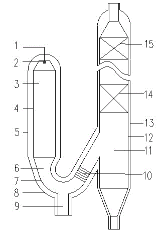
[0045] Such as figure 1 As shown, the gasification reaction chamber 3 is a vertical cylindrical space surrounded by the wall surface 4 of the reaction chamber. The fuel and gasification agent from the delivery pipeline 1 are sprayed into the reaction chamber through the burner 2, and the gasification reaction occurs, producing carbon monoxide and Synthesis gas with hydrogen as the main component. Most of the minerals in the fuel are in the molten liquid state and flow down the wall of the reaction chamber, and the other part is carried by the high-temperature syngas in the form of molten droplets. Outlets for synthesis gas and slag are located at the bottom of the reaction chamber. Next to the outlet at the bottom of the reaction chamber, a "U"-shaped slag chamber 6 is set. The "U"-shaped slag chamber is a U-shaped pipe surrounded by the wall surface 7 of the slag chamber. Refractory material" structure. The molten slag flowing out from the outlet at the bottom of the react...

Embodiment 2

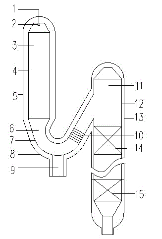
[0049] Such as figure 2 As shown, the specific action principle of embodiment 2 is the same as that of embodiment 1, except that after the gas enters the syngas cooler, since the synthesizer cooler can be designed as different gas flow directions according to needs, in this embodiment, the gas flows downward flow, and the wall of the syngas cooler is a membrane water wall structure. In the syngas cooler, a certain number and form of radiation heating surfaces 14 and convective heating surfaces 15 can be arranged in sequence along the flow direction, and finally the syngas cooled to a certain temperature is drawn out from the lower gas outlet of the syngas cooler.


PUM


Abstract

The invention discloses a total heat recovery type synthesis gas cooler with a residue chamber. The total heat recovery type synthesis gas cooler comprises a synthesis gas cooler and a U-shaped residue chamber, wherein one end of the U-shaped residue chamber is communicated with the synthesis gas cooler, and a residue outlet is arranged on the bottom part of the residue chamber. The total heat recovery type synthesis gas cooler further comprises a gasification reaction chamber, and the bottom outlet of the gasification reaction chamber is communicated with the other end of the U-shaped residue chamber. A residue catcher is arranged in a passage in which the residue chamber turns to the synthesis gas cooler. The total heat recovery type synthesis gas cooler with residue chamber disclosed by the invention is used for effectively separating liquid slag and ash drops from the synthesis gas before the high temperature synthesis gas enters the synthesis gas cooler so as to solve such common problems of the synthesis gas cooler as scorification, blockage and contamination, and the like; and ash concentration in the synthesis gas is greatly decreased, so that the attrition of a convection heating surface is alleviated, the gas flow rate in the synthesis gas cooler can be correspondingly increased, the heat exchange is reinforced, the equipment is more compact and the production cost is lowered.

Description

technical field [0001] The invention relates to a full heat recovery syngas cooler with a slag chamber, which belongs to the technical field of coal gasification and integrated coal gasification combined cycle power generation. [0002] Background technique [0003] The outlet temperature of the syngas of the entrained bed gasifier is generally above 1300°C, and the sensible heat of the outlet high-temperature syngas accounts for about 20-25% of the calorific value of the fuel entering the furnace, and the rest is mainly CO and H 2 chemical energy. The recovery of high-temperature sensible heat of syngas is very important to improve the energy utilization efficiency of the whole system. Due to the liquid slag discharge, the high-temperature syngas carries liquid slag and ash droplets, which can easily cause slagging and blockage of the heating surface, so the high-temperature sensible heat recovery of the syngas is very difficult. In order to effectively recover the high-...

Claims


Application Information

Patent Timeline
IPC IPC(8): C10J3/84C10J3/72C10K1/04
CPCY02E20/18Y02P20/10
Inventor 李维成孙登科王锦生陈阳臧平伟李由聂立
Owner DONGFANG BOILER GROUP OF DONGFANG ELECTRIC CORP
Why Eureka
Try Eureka