
Two-stage rotational-flow air flotation separator

A cyclone air flotation and separator technology, which is used in liquid separation, separation methods, flotation water/sewage treatment, etc., can solve the problems of inability to meet the requirements of oily sewage treatment, large equipment volume, increased investment and operating costs, etc.

Active Publication Date: 2014-07-30
HUNAN ZHONGKE FUBANG TECH
View PDF5 Cites 0 Cited by
  • Summary
  • Abstract
  • Description
  • Claims
  • Application Information

AI Technical Summary

Problems solved by technology

[0003] Traditional air flotation separation technology, the residence time is basically between 15 minutes and 30 minutes. Due to the long residence time, the equipment is large in size and occupies a large area, which limits its application range, especially for compact equipment. More stringent requirements for testing sites (such as FPSO, adopting platforms, etc.)
Secondly, the traditional air flotation separation efficiency is generally about 80%, which is increasingly unable to meet the requirements of high oil removal efficiency.
[0004] The hydrocyclone is separated by the density difference between the oil droplet and the sewage. When the density of the oil droplet is getting closer to the sewage density and the diameter of the oil droplet is smaller, the degreasing effect of the hydrocyclone will be greatly reduced, which cannot meet the requirement of oily sewage. Processing requirements; at the same time, hydrocyclones have higher requirements on water inlet pressure, and for low-pressure conditions, power equipment needs to be added, which increases investment and operation costs. Thirdly, hydrocyclones have low fluctuation resistance and poor adaptability

Method used


Image

  • Two-stage rotational-flow air flotation separator
  • Two-stage rotational-flow air flotation separator
  • Two-stage rotational-flow air flotation separator

Examples


Embodiment Construction

[0019] The specific implementation manner of this patent will be described in further detail below in conjunction with the accompanying drawings.

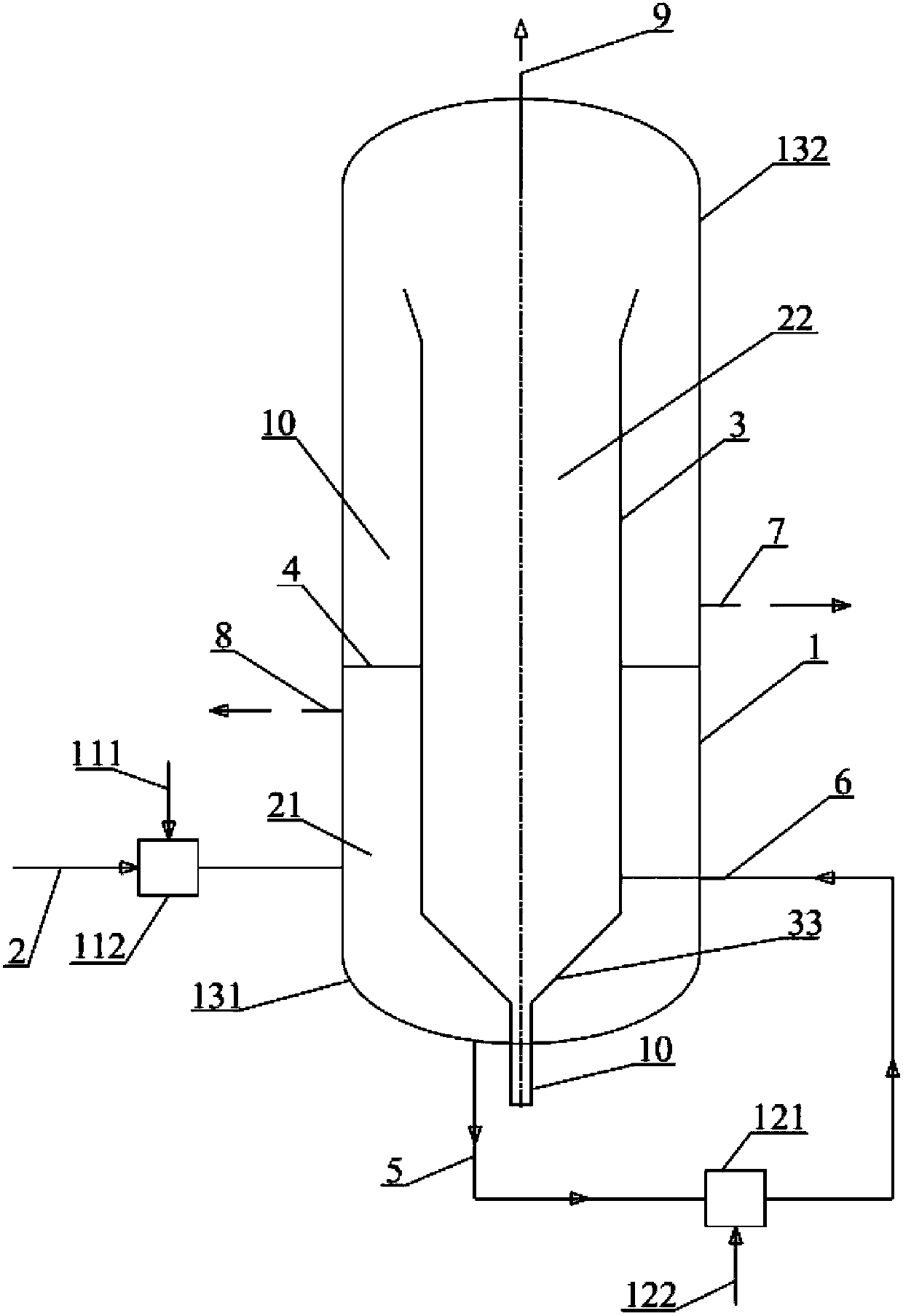
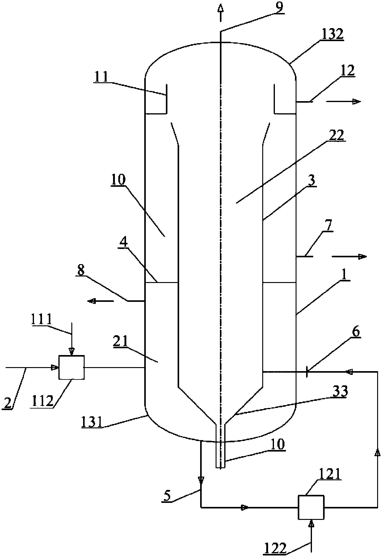
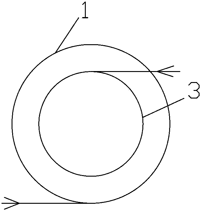
[0020] Such as figure 1 As shown, a two-stage cyclone air flotation separator includes a tank body 1, a primary water inlet 2, an inner cylinder 3, a partition 4, a primary water outlet 5, a secondary water inlet 6, and a secondary water outlet 7 , the first-level scum outlet 8, the second-level scum outlet 9 and the sewage outlet 10. The inner cylinder 3 is coaxially arranged with the tank body 1, and the tank body 1 is divided into a primary separation area and a secondary separation area by the inner cylinder 3, and a A partition 4, which divides the space between the inner wall of the tank body 1 and the outer wall of the inner cylinder 3 into a lower primary flotation zone 21 and an upper secondary flotation zone 22 that are independent and sealed up and down, The partition 4 is set at a position 1 / 3 to 1 / 2 of the height of ...


PUM


Abstract

The invention discloses a two-stage rotational-flow air flotation separator, comprising a tank, wherein the tank is provided with a first-stage water outlet and at least one first-stage water inlet; an inner barrel is installed in the tank; an opening is formed at the upper end of the inner barrel; at least one second-stage water inlet is formed in the lower side of the inner barrel; the first-stage water outlet of the tank is communicated with the second-stage water inlet of the inner barrel via a pipeline; a second-stage dross outlet is formed at a position corresponding to the opening of the inner barrel, at the upper end of the tank; a clapboard is installed between the inner wall of the tank and the outer wall of the inner barrel; and the clapboard is used for dividing a space between the inner wall of the tank and the outer wall of the inner barrel into an upper part and a lower part. The two-stage rotational-flow air flotation separator disclosed by the invention is compact in structure, reduced in equipment volume and floor area, good in oil removal effect and suspended particle removal effect, suitable for the application fields of various oily water separation, suspended matter separation, and the like, and especially suitable for treatment for oily sewage in the petrochemical industry.

Description

technical field [0001] The invention relates to a double-stage cyclone air flotation separator. Background technique [0002] Petroleum and petrochemical industries will produce a large amount of oily sewage in the production process of oil extraction, treatment, crude oil refining, etc. The commonly used oil-water separation methods mainly include: gravity sedimentation separation, air flotation, hydrocyclone separation, filtration separation and other methods. These methods have their own advantages and disadvantages and scope of application. The air flotation separation technology has been widely used in the treatment of petroleum and chemical oily sewage due to its mature technology, wide application scope, low investment, and low operation and maintenance costs. [0003] Traditional air flotation separation technology, the residence time is basically between 15 minutes and 30 minutes. Due to the long residence time, the equipment is large in size and occupies a large ar...

Claims


Application Information

Patent Timeline
Patent Type & Authority Patents(China)
IPC IPC(8): C02F1/38C02F1/24C02F1/40
Inventor 陈小珍张旭辉陈昌军
Owner HUNAN ZHONGKE FUBANG TECH
Learn More