Receiving device, signal processing device and signal processing method
A technology of receiving equipment and receivers, applied in the direction of modulated carrier system, transmission system, multi-frequency code system, etc., to achieve the effect of eliminating throughput and reducing the number of processes
- Summary
- Abstract
- Description
- Claims
- Application Information
AI Technical Summary
Problems solved by technology
Method used
Image
Examples
no. 1 approach
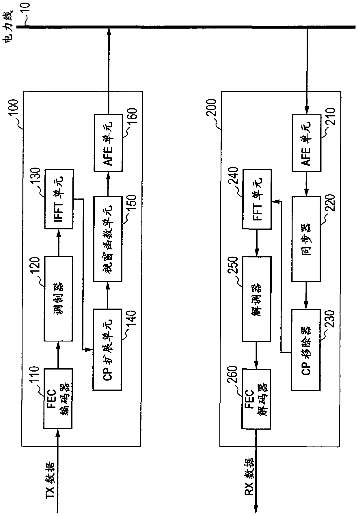
[0044] Hereinafter, a first embodiment of the present invention will be described with reference to the accompanying drawings. figure 1is a block diagram of the power line communication system 1000 according to the first embodiment of the present invention. In the power line communication system 1000 , a transmitting device 100 and a receiving device 200 are communicably coupled through a power line 10 .
[0045] First, the configuration of the transmitting device 100 is described. The transmitting device 100 includes a forward error correction (FEC) encoder 110, a modulator 120, an inverse fast Fourier transform (IFFT) unit 130, a cyclic prefix (CP) extension unit 140, a window function unit 150, and an analog front end (AFE) Unit 160.
[0046] The FEC encoder 110 applies an encoding process to TX data by using a preceding error correction code such as a convolutional code.
[0047] Modulator 120 applies modulation to the encoded TX data. Here, the modulator 120 performs...
no. 2 approach
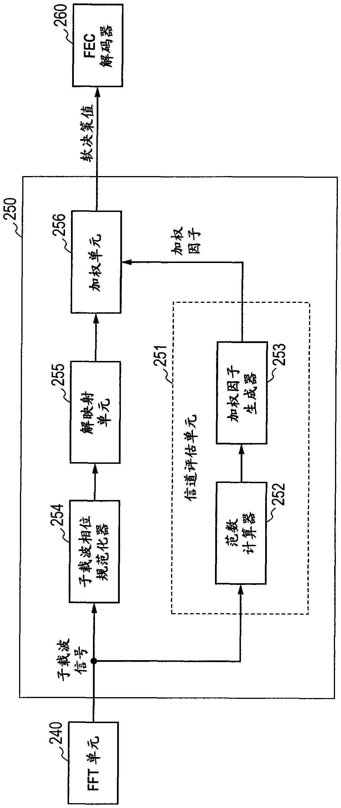
[0075] The receiving device according to the second embodiment is designed to generate weighting factors by calculating the variance of the norm as a variation of the norm. Description is made below with reference to the accompanying drawings. Note that a description part of the configuration described in the first embodiment is omitted for clarity of the present invention.
[0076] Figure 4 is a block diagram of the demodulator 350 according to the second embodiment. In the demodulator 350 , a weighting factor generator 353 generates weighting factors based on the norm calculated in the norm calculator 252 . The weighting factor generator 353 includes a norm variance calculator 354 and a norm variance storage unit 355 .
[0077] The norm variance calculator 354 calculates the variance of the norm for each subcarrier output from the norm calculator 252 . if x k is the norm of the subcarrier signal in the kth symbol in a certain subcarrier, then the norm variance calculat...
no. 3 approach
[0090] In the second embodiment described above, the variance calculated based on the norm of each subcarrier is used as a weighting factor for weighting. Such as Figure 6 As shown in , this is because when the expected value of the norm μ is large enough relative to σ (ie, the SN is large enough), it can be approximated as μ 2 Signal power, σ 2 noise power.
[0091] However, when the expected value is close to σ (i.e., when no SN is achieved), σ 2 The approximation of the noise power does not have large deviations, while μ 2 The approximation of signal power is not true. Such as Figure 7 As shown in , this is because when the noise N is large, the ratio of elements of the phase that is folded beyond 180 degrees and added increases. Such contributions are not negligible, and therefore, there is a difference between the observed values and the probability density function.
[0092] Therefore, the receiving device according to the third embodiment of the present inven...
PUM
 Abstract
Description
Claims
Application Information
 - R&D
- Intellectual Property
- Life Sciences
- Materials
- Tech Scout
- Unparalleled Data Quality
- Higher Quality Content
- 60% Fewer Hallucinations
Browse by: Latest US Patents, China's latest patents, Technical Efficacy Thesaurus, Application Domain, Technology Topic, Popular Technical Reports.
© 2025 PatSnap. All rights reserved.Legal|Privacy policy|Modern Slavery Act Transparency Statement|Sitemap|About US| Contact US: help@patsnap.com


