
Device for recovering waste heat and supplying steam through multistage dilatation flashing

A steam and flash evaporation technology, which is applied in the field of high-temperature waste heat utilization, can solve the problems of heat absorption affecting heat generating devices, high operating costs, and long distances between hot spots of production and hot spots of consumption, etc., and achieves insensitivity to heat load fluctuations and automatic adjustment of production The effect of stable steam volume and steam pressure

Active Publication Date: 2013-05-29
NINGBO JINHAI CHENGUANG CHEM +1
View PDF9 Cites 17 Cited by
  • Summary
  • Abstract
  • Description
  • Claims
  • Application Information

AI Technical Summary

Problems solved by technology

[0003] For example, some enterprises recover heat energy by exchanging heat with cold materials, but in actual use, the supply and demand of the two often do not match, and it is difficult to completely recover the heat, which makes the use of waste heat insufficient.
Moreover, the production hotspots and usage hotspots of some enterprises are far away from each other, and the two cannot be connected, and the operation cost of connecting them is very high.
In addition, when the hot spot heat is unstable, it will affect the heat of the heat generating device to be absorbed in time, causing the heat in it to be wasted

Method used


Image

  • Device for recovering waste heat and supplying steam through multistage dilatation flashing
  • Device for recovering waste heat and supplying steam through multistage dilatation flashing

Examples


Embodiment 1

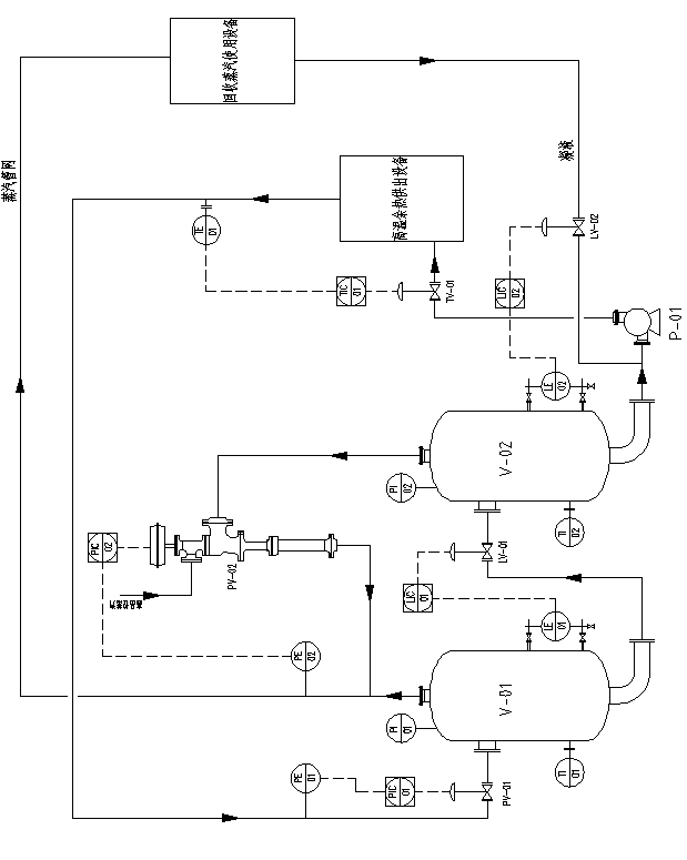
[0032] figure 1 Structural block diagram of waste heat recovery and steam supply device for secondary expansion flash evaporation, including: primary flash tank V-01, secondary expansion flash tank V-02, hot water circulation pump P-01, hot water pipe network Pressure regulating valve PV-01, steam injection heat pump PV-02, hot water main pipe temperature control system TIC-01 (including temperature regulating valve TV-01 and temperature transmitter TE-01), primary flash tank V-01 The liquid level control system LIC-01 (including liquid level regulating valve LV-01 and liquid level transmitter LE-01) is installed on the top, and the liquid level control system LIC-02 ( Including liquid level regulating valve LV-02 and liquid level transmitter LE-02), all devices are connected by pipelines, in which water (or low-pressure steam or steam-water mixture) is used as the heat carrier, and hot water is preferred Heat carrier, safe and stable.

[0033] As a further improvement, temp...

Embodiment 2

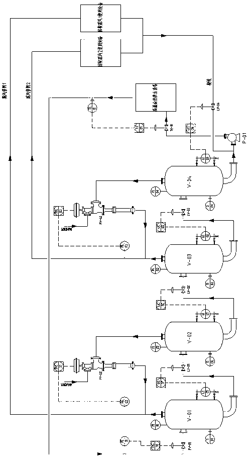
[0043] figure 2 Schematic diagram of the simplified structure for recovering waste heat and supplying steam for four-stage expansion flash evaporation, including: one-stage flash tank V-01, two-stage expansion flash tank V-02, three-stage flash tank V-03, four-stage expansion Flash tank V-04, hot water circulation pump P-01 (multiple equipment can be used according to process characteristics), including pressure regulating valve PV-01, steam injection heat pump PV-02, including steam injection heat pump PV-03, Each flash tank is equipped with a liquid level control system: liquid level control system LIC-01 (including liquid level control valve LV-01 and liquid level transmitter LE-01), LIC-02 (including liquid level control valve LV-02 and liquid level transmitter LE-02), LIC-03 ​​(including liquid level control valve LV-03 and liquid level transmitter LE-02), LIC-04 (including liquid level control valve LV-04 and Liquid level transmitter LE-02), hot water main pipe tempera...


PUM


Abstract

The invention provides a device for recovering waste heat and supplying steam through multistage dilatation flashing. Hot water (or low-pressure steam or steam-water mixture two-phase flow) is used as a circulatory medium to absorb the high-temperature waste heat in the device; the high-temperature waste heat is changed into the steam with a pressure energy level, capable of being used by the device, through flashing, the dilatation flashing and steam jet type heat pump pressurization; and the steam is changed into condensate and returned to the system after being used, the steam and the low-temperature hot water after the dilatation flashing are delivered into the device to absorb high-temperature waste heat, and closed recirculation is formed. According to the device for recovering the waste heat and supplying the steam through the multistage dilatation flashing, energy can be fully absorbed and delivered in a long distance to heat using sites according to needs, the heat can be stably supplied, and the device can be suitable for waste heat recovery and steam supply of heat using units with used heat changed.

Description

technical field [0001] The invention belongs to the technical field of high-temperature waste heat utilization, and in particular relates to a device for recovering waste heat and supplying steam by multi-stage expansion flash evaporation. Background technique [0002] There are often some high-temperature waste heat in chemical equipment, such as the gas phase at the top of the rectification tower, the outlet material of the reactor, and the high-temperature material in the tower kettle, etc., all contain a large amount of heat energy. Many enterprises use air cooling or circulating water cooling to waste energy. waste. How to recover the heat and make full use of it is a very important energy-saving measure, but there are many problems in practical application. [0003] For example, some enterprises recover heat energy by exchanging heat with cold materials, but in actual use, the supply and demand of the two often do not match, and it is difficult to fully recover th...

Claims


Application Information

Patent Timeline
Patent Type & Authority Applications(China)
IPC IPC(8): F22B3/04
CPCY02P80/15
Inventor 阎尔平
Owner NINGBO JINHAI CHENGUANG CHEM
Learn More