
Sounding Reference Signal Transmission in Carrier Aggregation

A technique for sounding reference symbols and carrier aggregation, which is applied in the directions of pilot signal allocation, signaling allocation, transmission path sub-channel allocation, etc., and can solve problems such as high transmission power

Active Publication Date: 2016-08-03
BLACKBERRY LTD
View PDF3 Cites 0 Cited by
  • Summary
  • Abstract
  • Description
  • Claims
  • Application Information

AI Technical Summary

Problems solved by technology

However, because of the additional SRS transmission on CC1 along with the PUSCH transmission on CC2, the transmit power is greater than the maximum power in the last symbol

Method used


Image

  • Sounding Reference Signal Transmission in Carrier Aggregation
  • Sounding Reference Signal Transmission in Carrier Aggregation
  • Sounding Reference Signal Transmission in Carrier Aggregation

Examples


Embodiment Construction

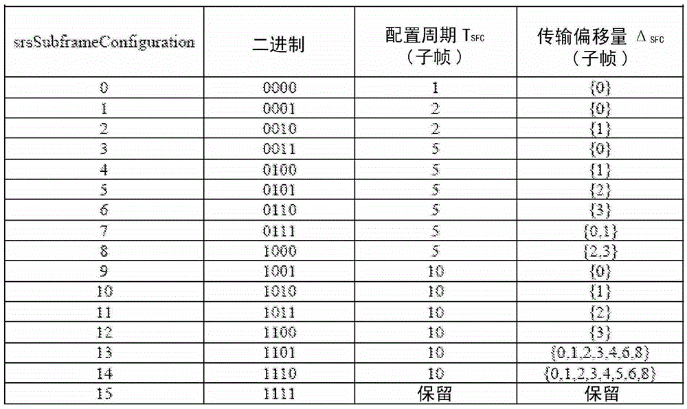
[0039] References collectively referred to as Figure 6 Figure 6A with 6B , Shows a block diagram of a configuration example of a cell-specific SRS subframe. More specifically, a method for reducing the overhead of signaling SRS subframes in carrier aggregation is explained. Although the UE expects to transmit SRS for different ULCCs in different subframes to avoid peak-to-average power ratio (PAPR) problems, it is beneficial to allocate the same cell-specific SRS subframes among different ULCCs. Such as Figure 6A As shown in, because all ULCCs belong to the same eNB, it is expected that the uplink subframes between different ULCCs are time aligned. Figure 6A An example is shown when the cell-specific SRS subframes are aligned among multiple CCs, and Figure 6B An example is shown when the cell-specific SRS subframe is different among multiple CCs.

[0040] in Figure 6A In the cell-specific SRS subframe, certain areas (for example, the first part of ULCC1 subframes 1, 3, and 5...


PUM


Abstract

A cell-specific sounding reference symbol (SRS) subframe configuration and UE-specific SRS configuration are defined for carrier aggregation. For the cell- specific SRS subframe configuration, the same cell-specific SRS subframes are configured for all uplink (UL) carrier components (CCs). For the UE-specific SRS configuration, different configurations are applied for UL CCs. Also, to reduce signaling overhead, the different UE-specific SRS configuration is signaled by using an offset on top of the UE-specific SRS configuration of a primary component carrier (PCC).

Description

Technical field [0001] The present invention generally relates to data transmission in a mobile communication network, and more specifically to sounding reference signal (SRS) transmission in carrier aggregation. Background technique [0002] In a known wireless communication system, a base station or a transmitting device in an access device transmits signals in a geographic area called a cell. As technology has evolved, more advanced devices have been introduced that can provide services that were not possible in the past. The advanced equipment may include, for example: E-UTRAN (Evolved Universal Terrestrial Radio Access Network) Node B (eNB), base station, or other systems and equipment. Such advanced or next-generation equipment is often referred to as Long Term Evolution (LTE) equipment, and a packet-based network using such equipment is often referred to as Evolved Packet System (EPS). An access device is any component that can provide a user agent (UA) such as a user eq...

Claims


Application Information

Patent Timeline
Patent Type & Authority Patents(China)
IPC IPC(8): H04L5/00H04W4/06
CPCH04L5/0007H04L5/001H04L5/0048H04L5/0053
Inventor 许允亨房慕娴迈克尔·约恩·巴克利马克·厄恩肖蔡志军
Owner BLACKBERRY LTD
Learn More