
Construction method of anti-floating locating system of cast-in-place concrete hollow floorslab steel tube

A technology of hollow floor slab and construction method, which is applied to the preparation of floor slabs, formwork/formwork/work frames, and building components on site, and can solve the problems of the decline in the quality of concrete floor slabs, the protection of prefabricated hollow pipes, and the turnover times of floor slabs Few other problems, to achieve the effect of good construction appearance quality, stable formwork anti-floating system, and high construction efficiency

Active Publication Date: 2013-05-22
CHINA 22MCC GROUP CORP +1
View PDF3 Cites 0 Cited by
  • Summary
  • Abstract
  • Description
  • Claims
  • Application Information

AI Technical Summary

Problems solved by technology

However, in the past construction technology of cast-in-place concrete hollow slabs, there were few turnover times of slab formwork, and a large number of iron wires had to be manually processed, which greatly reduced economic benefits and reduced the quality of concrete slabs.
At the same time, the protection of prefabricated hollow pipes is not optimistic

Method used


Image

  • Construction method of anti-floating locating system of cast-in-place concrete hollow floorslab steel tube
  • Construction method of anti-floating locating system of cast-in-place concrete hollow floorslab steel tube
  • Construction method of anti-floating locating system of cast-in-place concrete hollow floorslab steel tube

Examples


Embodiment Construction

[0027] The present invention will be further introduced below in conjunction with the accompanying drawings and embodiments.

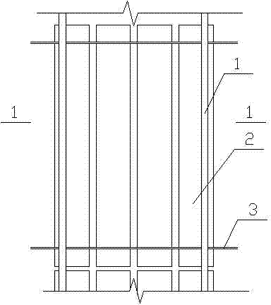
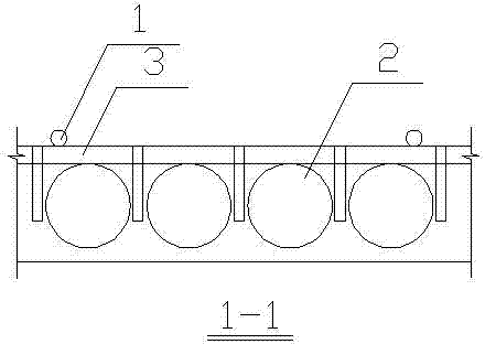
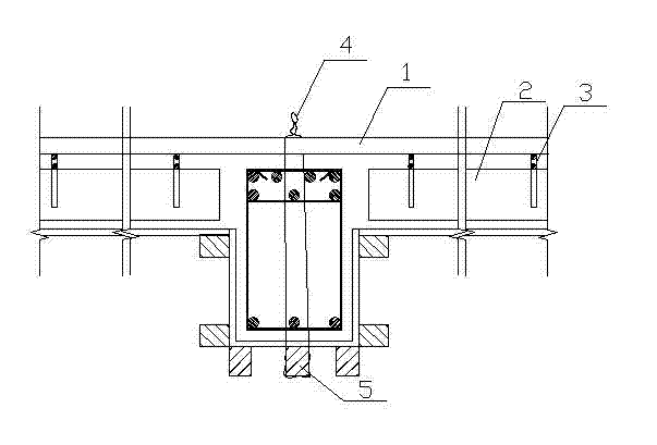
[0028] See attached Figure 1~4 , in the present embodiment, the construction method of the steel pipe anti-floating positioning system that limits the floating of the prefabricated hollow pipe in the hollow floor slab is carried out according to the following steps:

[0029] ①Establish the formwork support system according to the formwork support system selected in the construction plan;

[0030] ② After the formwork support frame is erected, support the beam bottom formwork, bind the beam reinforcement, install the beam side formwork, and finally install the roof formwork;

[0031] ③ After the floor formwork is installed and cleaned, mark the prefabricated hollow pipe 3 and the position line of the intercostal hidden beam, the position line of the bottom row of steel bars on the floor, the reserved hole for water and electricity, and the position li...


PUM


Abstract

The invention provides a construction method of an anti-floating locating system of a cast-in-place concrete hollow floorslab steel tube. The method comprises the following steps of: bracing a beam bottom template, binding beam steel, installing a beam side template and finally installing a top plate template; marking position lines of all parts, water-electricity reserved holes and a position line of an embedded junction box on the templates; binding a hidden beam and plate bottom steel; embedding water-electricity conduits, wire boxes and sleeves; arranging an anti-floating point on the beam bottom template vertical to the laying direction of a prefabricated hollow tube, enabling an iron wire to pass through the templates and be connected with a template support system in a pulling way,and throwing off an end head from the upper part of the iron wire; installing the prefabricated hollow tube, arranging an F-shaped locating fixture vertical to the laying length direction of the prefabricated hollow tube, and controlling the horizontal displacement of the prefabricated hollow tube by using the F-shaped locating fixture; arranging a compression steel tube on a reinforcing mesh sheet, pouring concrete and maintaining; shearing off the iron wire and removing the compression steel tube. The anti-floating locating system of the steel tube is used for cast-in-place concrete hollow floorslab construction, the construction method is simple and the construction efficiency is high.

Description

technical field [0001] The invention relates to a construction method of a cast-in-place concrete hollow floor, in particular to a construction method of a steel pipe anti-floating positioning system for a cast-in-place concrete hollow floor that restricts floating of prefabricated hollow tubes in the hollow floor. Background technique [0002] With the continuous development of the construction industry and the emergence of new technologies, there are more and more buildings with large spans, large loads, and large spaces. Buildings with large spans, large loads, and large spaces are built with traditional building structures, and their weight is relatively large. Not conducive to earthquake resistance. The construction technology of cast-in-place concrete hollow slabs is a new technology of structural construction that has only been developed in China in recent years. As a key construction technology promoted by the Ministry of Construction at the end of the 20th century a...

Claims


Application Information

Patent Timeline
Patent Type & Authority Patents(China)
IPC IPC(8): E04G21/00E04G21/02E04G15/06E04G17/04E04B5/32
Inventor 苑宗双李建国
Owner CHINA 22MCC GROUP CORP
Learn More