Swivel head for chain conveying equipment

A technology of chain conveying and rotary head, which is applied in the field of rotary head, can solve the problems of complex structure of rotary head, low installation efficiency, consuming assembly man-hours, etc., and achieve the effect of reducing assembly man-hours, fast installation, and improving production efficiency

Pending Publication Date: 2019-11-05
WUXI ZHONGDING INTEGRATION TECH CO LTD
View PDF0 Cites 0 Cited by
  • Summary
  • Abstract
  • Description
  • Claims
  • Application Information

AI Technical Summary

Problems solved by technology

[0002] In warehousing and logistics equipment, especially on chain conveyors, it is usually necessary to install a rotary head. In the prior art, in order to install the rotary head, drilling, tapping and other process steps are required, and the structure of the rotary head is complicated, the installation efficiency is low, and the cost is high. Excessive assembly man-hours

Method used


Image

  • Swivel head for chain conveying equipment
  • Swivel head for chain conveying equipment
  • Swivel head for chain conveying equipment

Examples


Embodiment Construction

[0019] The present invention will be further described below in conjunction with specific drawings.

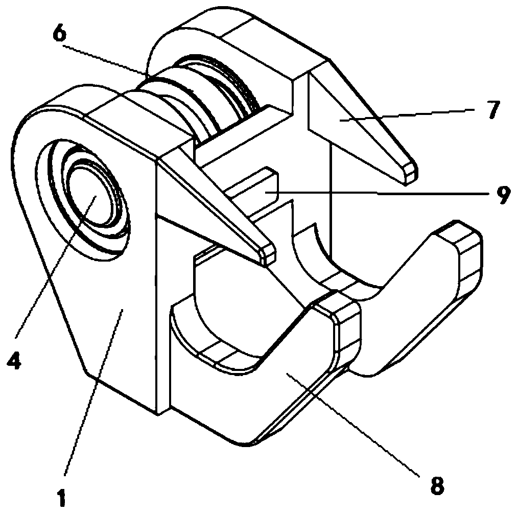
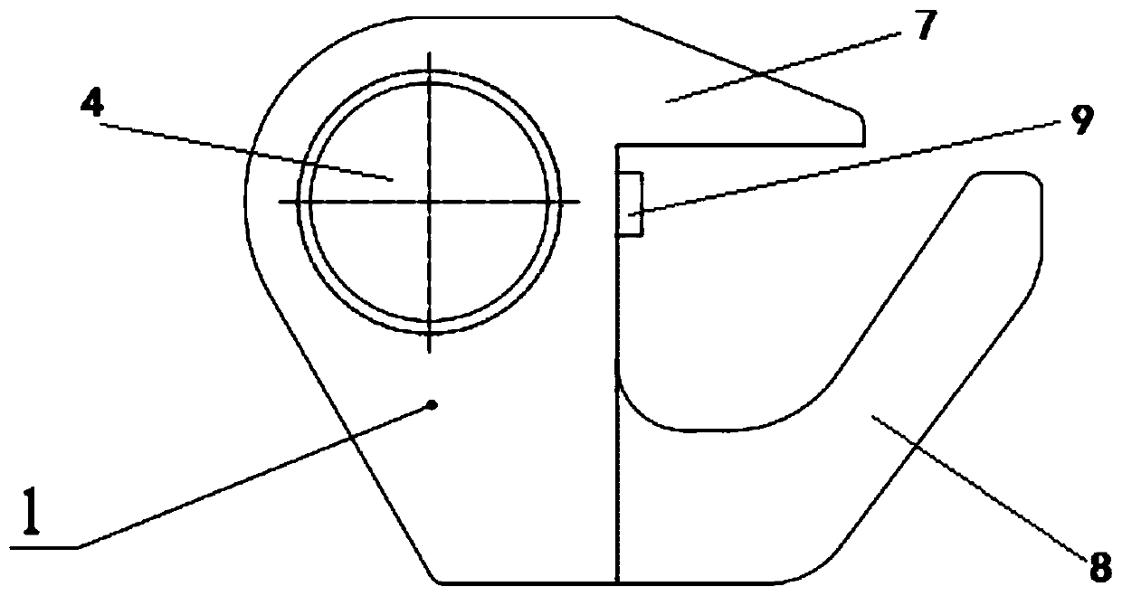
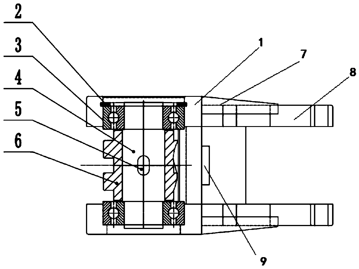
[0020] Such as figure 1 As shown, a rotary head used for chain conveying equipment includes a rotary head housing 1, a bearing 3, a shaft 4, a flat key 5 and a guide wheel 6, and the two ends of the rotary head housing 1 are respectively provided with bearings 3. A shaft 4 is set inside the two bearings 3, a guide wheel 6 is set on the shaft 4, and a flat key 5 is set between the shaft 4 and the guide wheel 6 to transmit torque; the side walls of the turret housing 1 are respectively Extend the upper clamping part 7 and the lower clamping part 8, and the side wall of the rotary head housing 1 between the upper clamping part 7 and the lower clamping part 8 is provided with a step 9; as Figure 4 As mentioned above, the upper clamping part 7, the lower clamping part 8 and the step part 9 can work together to clamp the upper wall of the main girder. The upper clamping part 7 an...


PUM


Abstract

The invention relates to a swivel head for chain conveying equipment. The swivel head comprises a swivel head shell body, bearings, shafts, flat keys and guide wheels, wherein the two ends of the swivel head shell body are provided with the bearings, the two bearings are provided with the shafts, the shafts are provided with the guide wheels, the flat keys are arranged between the shafts and the guide wheels and used for transferring torques; the side wall of the swivel head shell body extends backwards to form an upper clamping part and a lower clamping part, wherein a step piece is arrangedon the side wall of the swivel head shell body between the upper clamping part and the lower clamping part; and the upper clamping part, the lower clamping part and the step piece can cooperate together to clamp the upper wall of a main beam. According to the swivel head for the chain conveying equipment, drilling, tapping and other process steps can be omitted, and the positioning is carried outthrough clamping pieces and the step piece owned by the swivel head so as to complete the assembly.

Description

technical field [0001] The invention relates to a rotary head, in particular to a rotary head for chain conveying equipment, and belongs to the technical field of chain conveying. Background technique [0002] In warehousing and logistics equipment, especially on chain conveyors, it is usually necessary to install a rotary head. In the prior art, in order to install the rotary head, drilling, tapping and other process steps are required, and the structure of the rotary head is complicated, the installation efficiency is low, and the cost is high. Excessive assembly man-hours. Contents of the invention [0003] The object of the present invention is to overcome the deficiencies in the prior art and provide a rotary head for chain conveying equipment. Holders and steps are positioned and locked to complete assembly. [0004] According to the technical solution provided by the present invention: a rotary head for chain conveying equipment, including a rotary head housing, b...

Claims


Application Information

Patent Timeline
Patent Type & Authority Applications(China)
IPC IPC(8): B65G23/04
CPCB65G23/04
Inventor 王嘉辉张欢徐兴旺
Owner WUXI ZHONGDING INTEGRATION TECH CO LTD
Why Eureka
Try Eureka