
Wireless millimeter wave communication system with mobile base station

a millimeter wave and mobile base station technology, applied in the field of wireless millimeter wave communication system with mobile base station, can solve the problems of insufficient utilization of fiber optic trunk lines, etc., to achieve efficient utilization of low-frequency wireless internet access bandwidth, efficient utilization of millimeter wave trunk line bandwidth, and efficient utilization of low-frequency bandwidth

Inactive Publication Date: 2011-03-22
TREX ENTERPRISES CORP
View PDF2 Cites 102 Cited by
  • Summary
  • Abstract
  • Description
  • Claims
  • Application Information

AI Technical Summary

Benefits of technology

This solution enables rapid, low-cost deployment of additional cells and access points, supporting high data rates and efficient use of bandwidth, while maintaining reliability and flexibility in various weather conditions, and can be used for both cellular and Internet services.

Problems solved by technology

However, the construction of fiber optic trunk lines is expensive (sometimes very expensive) and the design and the construction of these lines can often take many months especially if the route is over private property or produces environmental controversy.
Often the expected revenue from the potential users of a particular trunk line under consideration does not justify the cost of the fiber optic trunk line.
In conjunction with the above availability requirements, weather-related attenuation limits the useful range of wireless data transmission at all wavelengths shorter than the very long radio waves.
At the higher, millimeter-wave frequencies, (i.e., 30 GHz to 300 GHz corresponding to wavelengths of 1.0 centimeter to 1.0 millimeter) where available bandwidth is highest, rain attenuation in very bad weather limits reliable wireless link performance to distances of 1 mile or less.
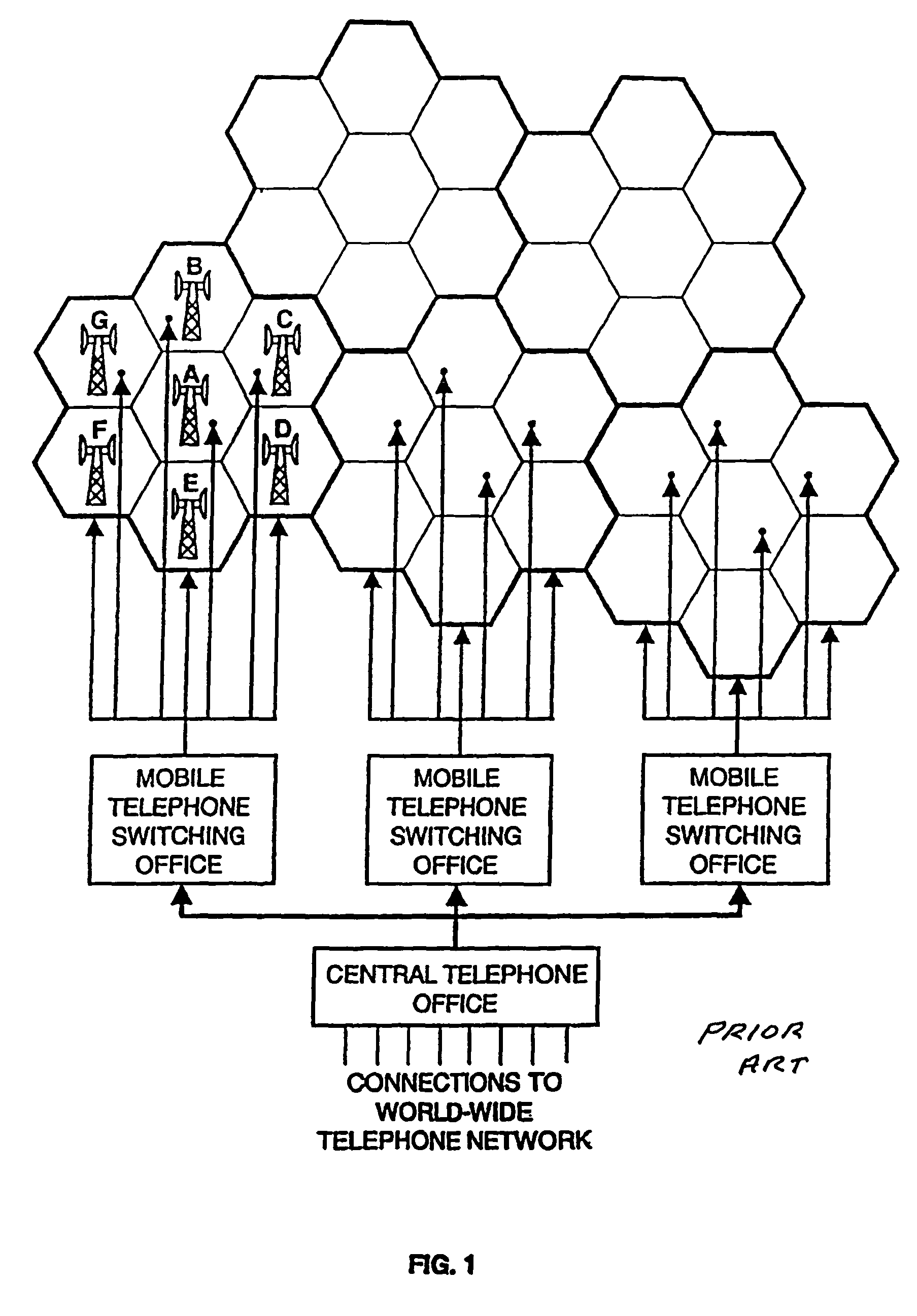
People in the past have avoided use of their cellular equipment because the cost was higher that their line telephones.

Method used


Image

  • Wireless millimeter wave communication system with mobile base station
  • Wireless millimeter wave communication system with mobile base station
  • Wireless millimeter wave communication system with mobile base station

Examples


Embodiment Construction

Millimeter Wave Trunk Lines

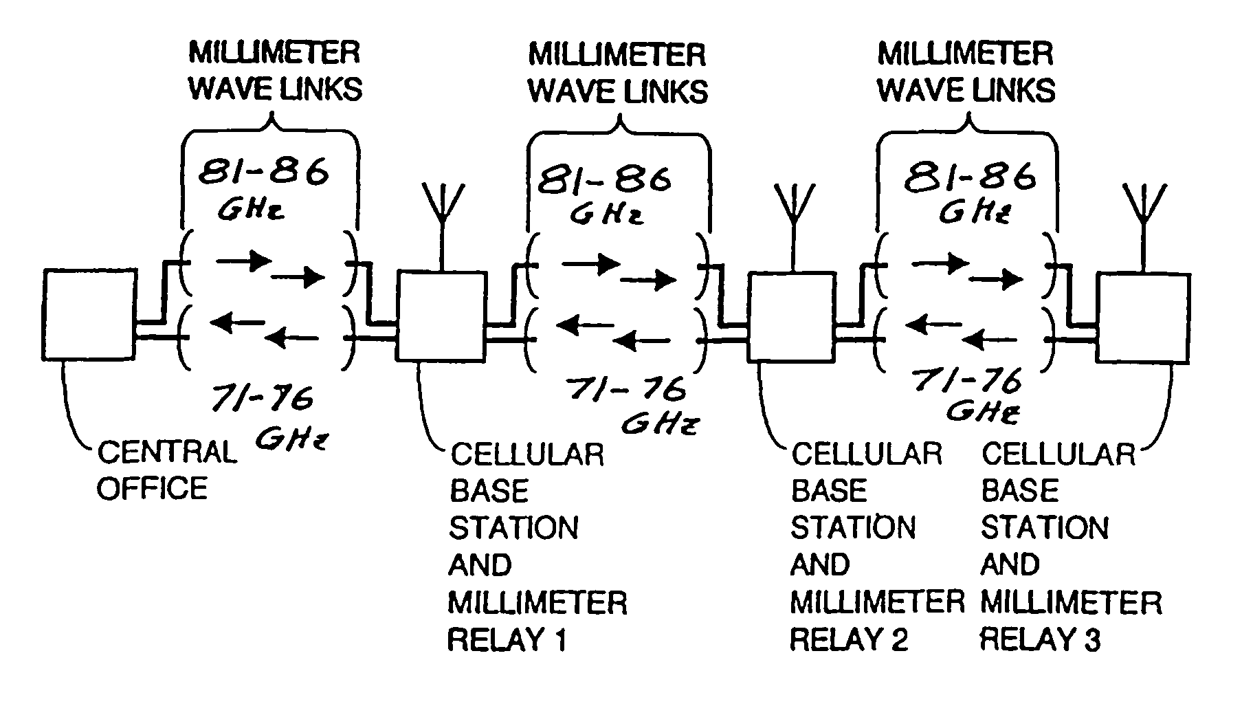
[0042]A first preferred embodiment of the present invention comprises a system of linked millimeter-wave radios which take the place of wire or fiber optic links between the cells of a cellular network. A second preferred embodiment of the present invention comprises a system of linked millimeter wave radios which take the place of wire or fiber optic links between wireless Internet access base stations or wireless computer networking base stations. The use of the millimeter-wave links can eliminate the need to lay cable or fiber, can be installed relatively quickly, and can provide high bandwidth normally at a lower cost than standard telecom-provided wires or cable. Since the millimeter-wave links simply up and down convert the signal for point-to-point transmission, the data and protocols used by the original signals are preserved, making the link ‘transparent’ to the user. These trunk lines can support a conventional system operating at standard cellul...


PUM


Abstract

A communication system providing wireless communication among wireless users through a number of cellular base stations. At least one of the base stations is a mobile base station in which low and high speed wireless transceivers are mounted on a temporarily stationary mobile vehicle such as a truck trailer or a truck. The system includes at least one connecting station with a millimeter wave wireless transceiver in communication with a fiber optic or high-speed cable communication network. The transceiver is adapted to communicate at millimeter wave frequencies higher than 60 GHz with another millimeter wave transceiver at one of the cellular base stations. Each of the base stations serves a separate communication cell. Each base station is equipped with a low frequency wireless transceiver for communicating with the wireless users within the cell at a radio frequency lower than 6 GHz and a millimeter wave wireless transceiver operating at a millimeter wave frequency higher than 60 GHz for communicating with another millimeter wave transceiver at another base station or a millimeter wave transceiver at said at the connecting station. The base stations are also equipped with data transfer means for transferring data communicated through the low frequency wireless transceiver to the millimeter wave wireless transceiver and for transferring data communicated through the millimeter wave wireless transceiver to the low frequency wireless transceiver. In preferred embodiments the system is a part of a telephone system, an Internet system or a computer network.

Description

[0001]The present invention relates to communication systems with wireless communication links and specifically to high data rate point-to-point links. This application is a continuation-in-part application of Ser. No. 11 / 249,787 filed Oct. 12, 2005 now U.S. Pat. No. 7,680,516 and Ser. No. 11 / 327,816 filed Jan. 6, 2006, both of which were continuations in part of Ser. No. 10 / 799,225 filed Mar. 12, 2004, now U.S. Pat. No. 7,062,293 which was a continuation-in-part of Ser. No. 09 / 952,591 filed Sep. 14, 2001, now U.S. Pat. No. 6,714,800 that in turn was a continuation-in-part of Ser. No. 09 / 847,629 filed May 2, 2001, now U.S. Pat. No. 6,556,836, and Ser. No. 09 / 882,482 filed Jun. 14, 2001, now U.S. Pat. No. 6,665,546.FEDERALLY SPONSORED RESEARCH[0002]This invention was made in the performance of a contract (Contract No. HQ0006-05-0006-DO0002) with the US Army and the United States Government has rights in the invention.BACKGROUND OF THE INVENTIONLocal Wireless Radio Communication[0003]...

Claims


Application Information

Patent Timeline
Patent Type & Authority Patents(United States)
IPC IPC(8): H04M1/00H04W84/00H04W92/20
CPCH04W92/20H04W84/005
Inventor LOVBERG, JOHN AJOHNSON, PAUL AKOREVAAR, ERIC
Owner TREX ENTERPRISES CORP
Learn More