
A booster circuit and its implementation method

A technology of booster circuit and realization method, which is applied to electrical components, adjusting electrical variables, instruments, etc., can solve the problems of damage to electronic components, high cost, and excessive capacitance of inrush current, so as to solve the problem of excessive inrush current and improve storage. energy, the effect of increasing the stored voltage

Active Publication Date: 2016-12-28
PHICOMM (SHANGHAI) CO LTD
View PDF4 Cites 0 Cited by
  • Summary
  • Abstract
  • Description
  • Claims
  • Application Information

AI Technical Summary

Problems solved by technology

Due to the existence of this requirement, products with this function often need to add some large-capacity electrolytic capacitors to store energy at the input end of the main power supply for energy storage, but there are two obvious problems in such a circuit ;The first problem is that due to the excessive capacitance, the excessive impact current at the moment of starting up will cause damage to the electronic components.
The second problem is that due to the high requirement for stored energy, the number of required capacitors will be relatively large, which will take up a lot of PCB (Printed Circuit Board, printed circuit board) area, so that the volume of the product is very large. bigger, more expensive

Method used


Image

  • A booster circuit and its implementation method
  • A booster circuit and its implementation method

Examples


Embodiment Construction

[0028] The present invention will be further described below in conjunction with the accompanying drawings and specific embodiments, but not as a limitation of the present invention.

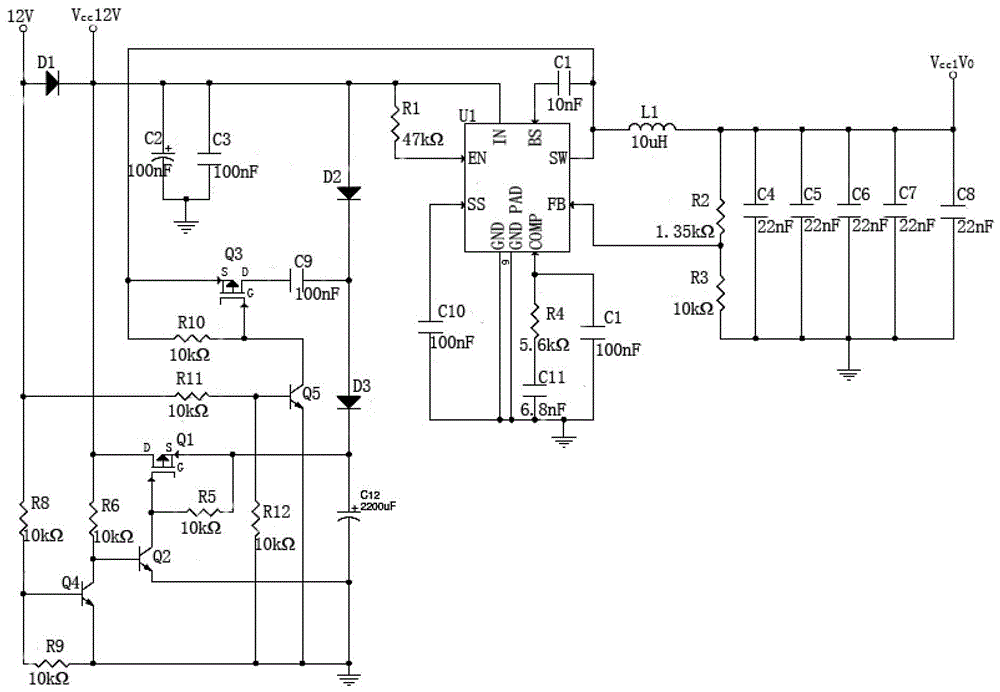
[0029] Such as figure 1 Shown is a schematic structural diagram of a boost circuit in an embodiment of the present invention, the boost circuit includes a power chip, a charging circuit, a discharging circuit and a basic circuit;

[0030] C in the picture n Indicates the capacitance, R n Indicates the resistance, L n Indicates the inductance, Q n Indicates CMOS tube, D n Indicates a diode, and in the embodiment of the present invention, the diodes are all Schottky diodes.

[0031] Such as figure 1 As shown, the power chip is a DC-DC boost chip. In the embodiment of the present invention, the specific model of the power chip is MP1484DS-LF-Z, which includes: SW pin (switching pin), FB pin (feedback pin), COMP pin (compensation pin), GND PAD pin (heat dissipation pin), GND pin (ground pin),...


PUM


Abstract

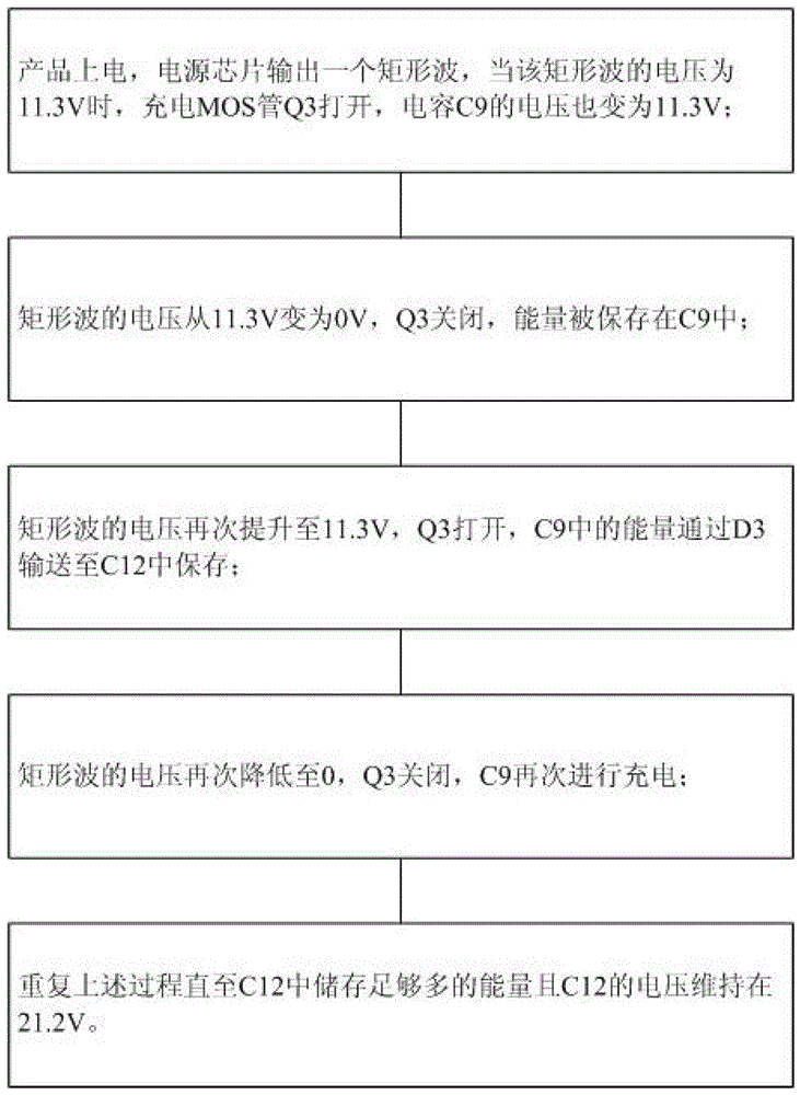
The invention discloses a boosted circuit and an implementation method, and belongs to the technical field of asymmetrical digital subscriber loop (ADSL) circuit design. The boosted circuit specifically comprises a power supply chip, a charging circuit and a discharging circuit. The charging circuit comprises a charging switch, a charging capacitor and a charging diode. The discharging circuit comprises a discharging switch and a discharging diode. The charging diode and the discharging diode are Schottky diodes. The power supply chip is a direct current (DC)-DC boosted chip. Charge-discharge operation on the circuit can be carried out by utilizing of the design of the boosted circuit. The boosted circuit has the advantages that storing voltage of an energy-storage capacitor can be improved through the boosted circuit, storing energy of capacitors with the same volume is synchronously improved, the problem of needing a large number of the capacitors is solved, and the problem that a surge current is overlarge in the moment of starting up is also solved.

Description

technical field [0001] The invention relates to the technical field of ADSL circuit design, in particular to a voltage boosting circuit and a realization method. Background technique [0002] At present, in ADSL (Asymmetric Digital Subscriber Line, asymmetric digital subscriber line) products and some other network products, due to the product's own characteristic requirements, it is required that the product can still maintain a short working time after power failure, so that the product can be in harmony with the local network. The server at the end communicates and releases the IP. Due to the existence of this requirement, products with this function often need to add some large-capacity electrolytic capacitors to store energy at the input end of the main power supply for energy storage, but there are two obvious problems in such a circuit ; The first problem is that due to the excessive capacitance, the excessive impact current at the moment of starting up will cause da...

Claims


Application Information

Patent Timeline
Patent Type & Authority Patents(China)
IPC IPC(8): H02M3/155
Inventor 黄杏陶燕范亚妮
Owner PHICOMM (SHANGHAI) CO LTD
Learn More