
Electromotor energy storage braking system and control method

A technology of energy storage braking and electric motor, which is applied in motor generator control, control system, fluid pressure actuation system components, etc., can solve the problems of large grid interference, small energy storage energy, inconvenient use, etc. Small, large energy storage, reducing the effect of heat generation

Active Publication Date: 2013-04-24
TAIYUAN UNIV OF TECH
View PDF5 Cites 19 Cited by
  • Summary
  • Abstract
  • Description
  • Claims
  • Application Information

AI Technical Summary

Problems solved by technology

[0003] The purpose of the present invention is to solve the technical problems of the existing energy storage equipment such as small energy storage energy, large interference to the power grid, and inconvenient use, and provide a device that can store and regenerate the kinetic energy of the motor braking process and the internal and external loads of the motor. Potential energy electric motor energy storage braking system and control method

Method used


Image

  • Electromotor energy storage braking system and control method
  • Electromotor energy storage braking system and control method

Examples


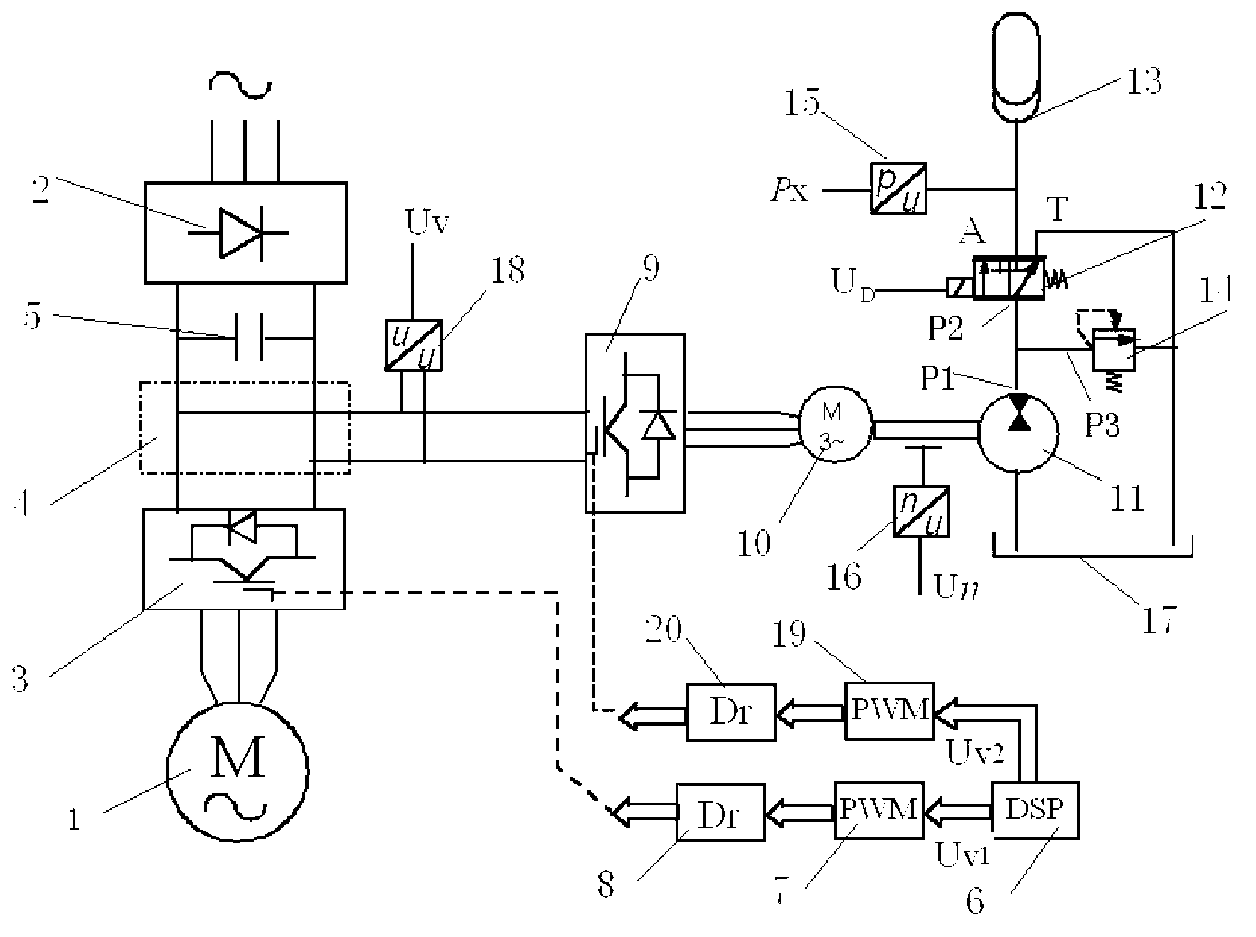
Embodiment 1

[0023] Such as figure 1 As shown, the motor energy storage braking system in this embodiment includes a main motor 1, a rectifier 2, a main inverter 3, a DC bus 4, a filter capacitor 5, a control computer 6, and the first pulse width signal (PWM) Generator 7 and the 1st driving module 8, wherein: it also comprises motor speed controller 9, electric / generator 10, hydraulic pump / motor 11, two-position three-way control valve 12, hydraulic accumulator 13, safety valve 14 , pressure sensor 15, speed sensor 16, hydraulic oil tank 17, voltage sensor 18, second pulse width signal (PWM) generator 19 and second driving module 20; the oil outlet P1 of the hydraulic pump / motor 11 is connected to the second through the pipeline The oil inlet P2 of the one-position three-way control valve 12 is connected with the oil inlet P3 of the safety valve 14, the oil return port T of the two-position three-way control valve 12 is connected with the hydraulic oil tank 17 through a pipeline, and the t...

Embodiment 2

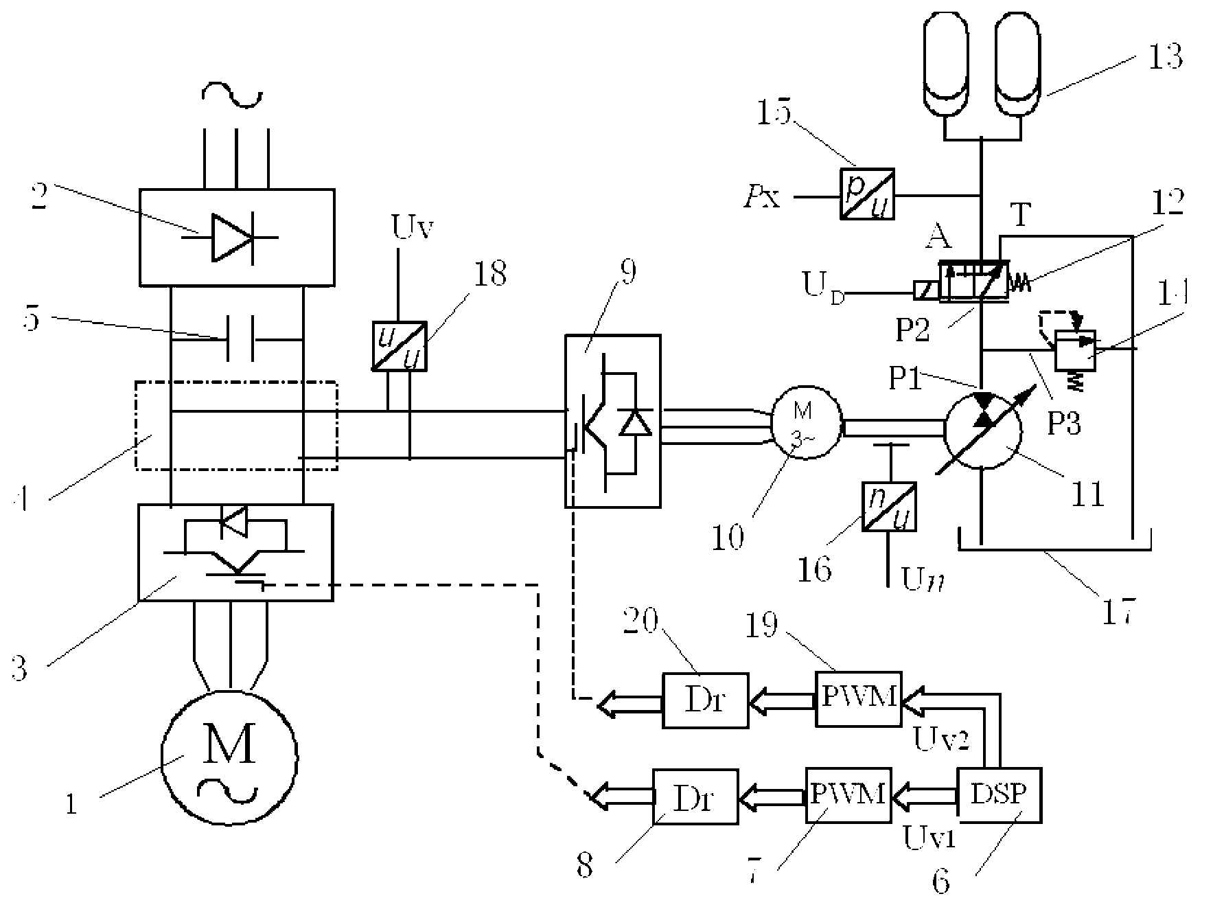
[0034] Such as figure 2 As shown, the motor energy storage braking system and control method in this embodiment are basically the same as the structure and control method in Embodiment 1, the difference is as follows: the quantitative hydraulic pump / motor 11 is electronically controlled variable displacement proportional hydraulic pump / motor instead; the two-position three-way control valve 12 adopts a pilot-operated electro-hydraulic reversing valve; the hydraulic accumulator 13 adopts an accumulator group composed of two accumulators.


PUM


Abstract

The invention relates to an electromotor energy storage braking system and a control method, and belongs to an energy storage braking system and a control method used for storing and recycling energy generated in the process of electromotor braking. The electromotor energy storage braking system and the control method mainly solve the technical problems that an existing energy storage device is small in stored energy, large in interference to a power grid, inconvenient to use and the like. The electromotor energy storage braking system comprises a main electromotor, a rectifier, a main inverter, a direct current bus, a filter capacitor, a control computer, a first pulse width signal generator and a first driving module, and further comprises a motor rotary speed controller, an electromotor or a generator, a hydraulic pump or a motor, a two-position three-way control valve, a hydraulic energy accumulator, a safety valve, a pressure sensor, a rotary speed sensor, a hydraulic oil tank, a voltage sensor, a second pulse width signal generator and a second driving module. The electromotor energy storage braking system and the control method have the advantages of achieving active control to the process of electromotor braking, saving energy, reducing consumption, achieving energy saving and emission reduction and the like.

Description

technical field [0001] The invention relates to a motor energy storage braking system and a control method, which belongs to an energy storage braking system and a control method that stores and regenerates the energy in the motor braking process, and is also suitable for motors with external gravity loads Drive System. Background technique [0002] To reduce the energy consumption of the motor drive system, in addition to improving the energy efficiency of the motor itself, the most commonly used technology is frequency conversion speed regulation to achieve energy supply on demand, that is, on the premise of meeting the requirements of speed, torque and dynamic response of production machinery and equipment, Minimize the input energy of the frequency conversion device. However, in industrial production, there are many processes that require the drag system to be able to quickly start, brake, and frequently rotate forward and reverse, or to release heavy loads with potenti...

Claims


Application Information

Patent Timeline
Patent Type & Authority Applications(China)
IPC IPC(8): H02P3/18F15B21/14
Inventor 权龙黄家海李斌姚李威
Owner TAIYUAN UNIV OF TECH
Learn More