
Armature plate and synchronous motor suitable for plate type coreless permanent magnet synchronous motor

A permanent magnet synchronous motor and armature disk technology, which is applied to synchronous motors with stationary armatures and rotating magnets, synchronous machine parts, etc. Complex process and other problems, to achieve the effect of avoiding manufacturing difficulties, light weight, and simple production process

Inactive Publication Date: 2013-05-15
常州市吉士电器有限公司
View PDF3 Cites 2 Cited by
  • Summary
  • Abstract
  • Description
  • Claims
  • Application Information

AI Technical Summary

Problems solved by technology

However, it is difficult to process and manufacture the armature windings of the existing disc-type coreless permanent magnet synchronous motors. The armature windings are made of multi-layer and multi-row windings of enameled wires. During the manufacturing process, high-precision winding machines and special cards are required. The production process is complex and the production efficiency is low, which limits the mass production of the motor at low cost. At the same time, in the disc permanent magnet synchronous motor, it is difficult to obtain an ideal sinusoidal distribution of the magnetic field in the air gap space of the motor

Method used


Image

  • Armature plate and synchronous motor suitable for plate type coreless permanent magnet synchronous motor
  • Armature plate and synchronous motor suitable for plate type coreless permanent magnet synchronous motor
  • Armature plate and synchronous motor suitable for plate type coreless permanent magnet synchronous motor

Examples


Embodiment Construction

[0016] The present invention will be further described now in conjunction with accompanying drawing. These drawings are simplified schematic diagrams only to illustrate the basic structure of the present invention in a schematic way, so they only show the components relevant to the present invention.

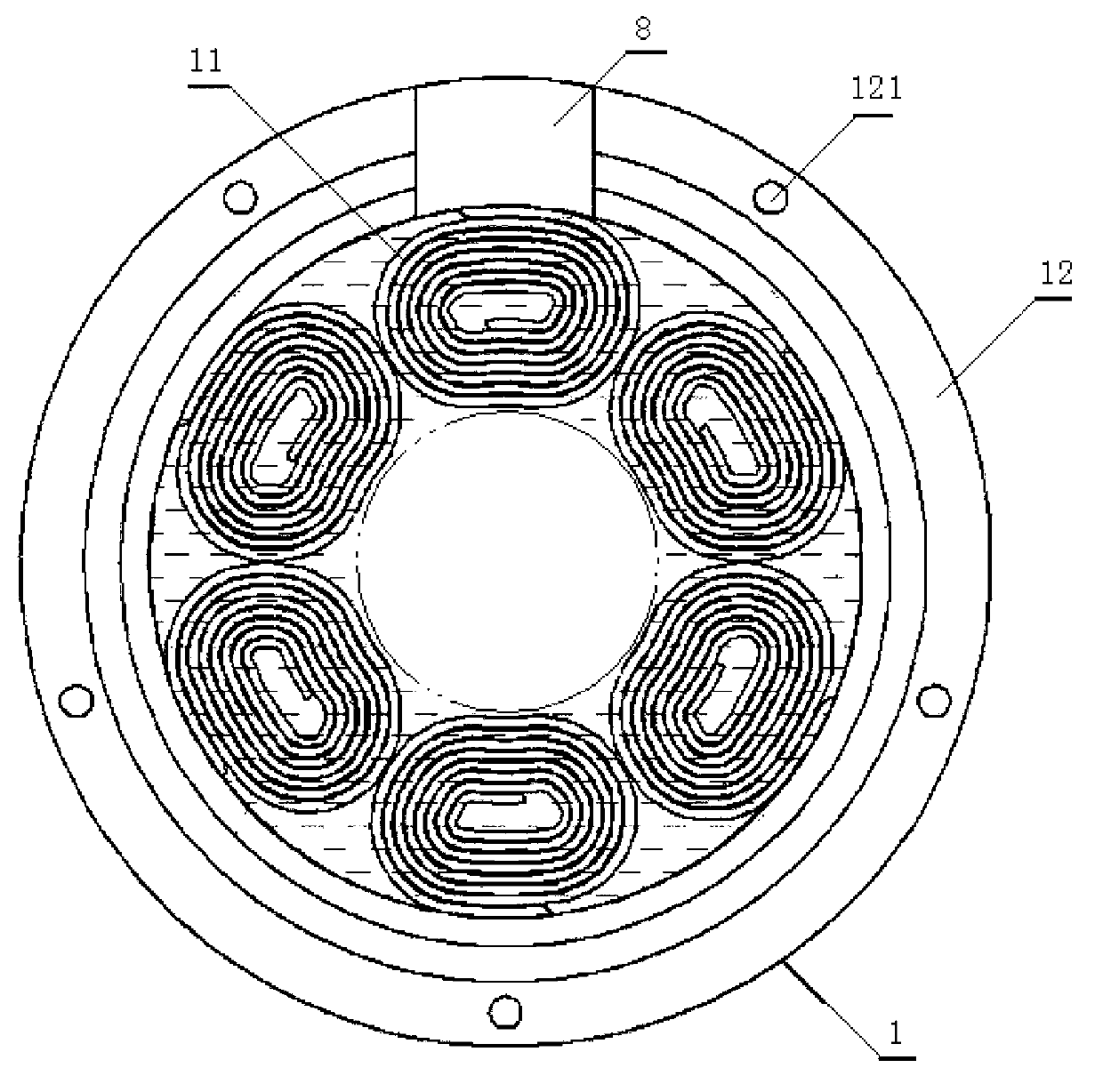
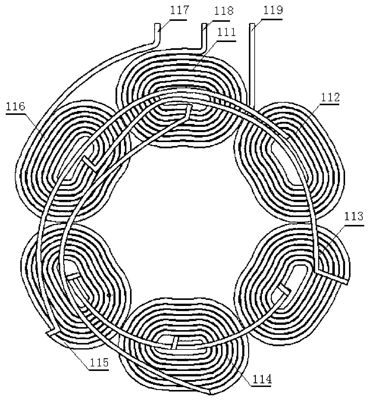
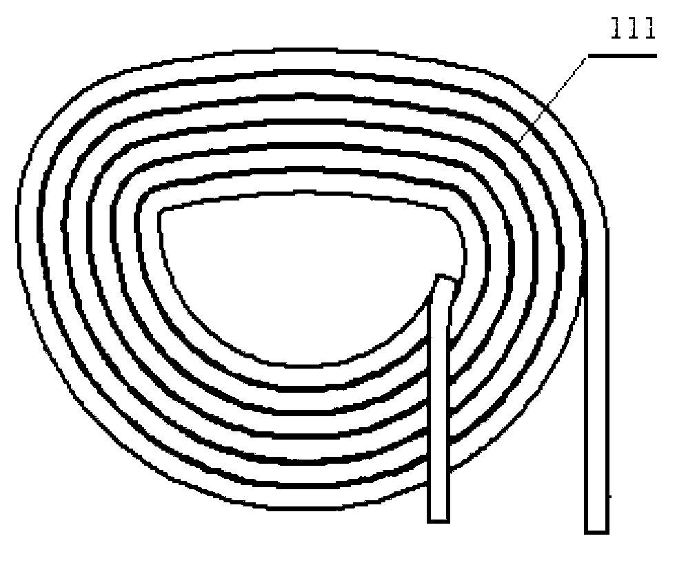
[0017] Such as figure 1 As shown, an armature disk suitable for a disk-type coreless permanent magnet synchronous motor has an armature 1, and the armature 1 has an armature disk body 12 and a coil winding 11. The armature disk body 12 is circular, and the coil The winding 11 is installed in the inner circle of the armature disk body 12. The coil winding 11 is composed of multiple winding coils. A single winding coil is wound by enamelled flat wire in a single row, and multiple winding coils are arranged in a single layer without overlapping. In a circular structure, the taps of a single winding coil are connected and drawn out according to the performance of the required synch...


PUM


Abstract

The invention relates to an armature plate and a synchronous motor suitable for a plate type coreless permanent magnet synchronous motor. The armature plate is provided with an armature. The armature is provided with an armature body and a coil winding. The coil winding is installed in an inner round of the armature body. The coil winding is composed of multiple winding coils. Each winding coil is formed by winding enamel covered sheet wires in a single row mode. The multiple winding coils are wound and arranged to be a round structure in a single layer mode without overlapping. The winding coils and the armature plate body are pressed and then form an annular body with a hole at the center. The armature of the synchronous motor is clamped between a left half shell body and a right half shell body which are installed oppositely. With the armature plate and the synchronous motor suitable for the plate type coreless permanent magnet synchronous motor, the tough situation that when an exiting plate type coreless permanent magnet synchronous motor is manufactured, multiple rows and multiple layers of windings are required is avoided. The armature plate and the synchronous motor suitable for the plate type coreless permanent magnet synchronous motor have the advantages of being simple in winding manner and manufacture technology, high in production efficiency and low in rejection rate. Meanwhile, the motor with the armature plates is light in weight and stable in rotation speed and yield is improved.

Description

technical field [0001] The invention relates to an armature disk and a synchronous motor suitable for a disc-type ironless permanent magnet synchronous motor. Background technique [0002] The disc permanent magnet synchronous motor is a motor with an ironless armature structure. Compared with a motor with an iron core armature structure, there is no torque ripple caused by cogging, the torque output is stable, and there is no magnetism. Hysteresis and eddy current loss, to achieve higher efficiency. However, it is difficult to process and manufacture the armature windings of the existing disc-type coreless permanent magnet synchronous motors. The armature windings are made of multi-layer and multi-row windings of enameled wires. During the manufacturing process, high-precision winding machines and special cards are required. tools, complex production process and low production efficiency, which limit the mass production of the motor at low cost. At the same time, in the di...

Claims


Application Information

Patent Timeline
Patent Type & Authority Applications(China)
IPC IPC(8): H02K21/02H02K21/12
Inventor 刘士杰冯相如宋冬平
Owner 常州市吉士电器有限公司
Learn More