


Quick Research
Generate reliable direction feasibility study reports for your R&D in just a few steps.

Technical Q&A
Discover and master advanced knowledge NOW. Basics, ideas, possibilities, all at once.

Find Solutions
As an expert in R&D theories, this can generate solutions to your technical problems instantly.

Evaluate Feasibility
Analyze your overall solution with one click, know your potential R&D risks in advance.

Monitor Landscape
Get weekly tech updates, stay abreast of the latest tech innovations and key insights.
Puffing device with two driving wheels and capable of accelerating dissolution of polymer
A polymer and double-moving wheel technology, which is applied in the direction of dissolving, dissolving, shaking/oscillating/vibrating mixer, etc., can solve the problem of long polymer dissolving time, large area occupied by the device volume, and polymer preparation process that cannot be applied on offshore platforms and other issues, to achieve the effect of shortening the dissolution time, reducing the space occupied, bearing weight, and accelerating the interaction
- Summary
- Abstract
- Description
- Claims
- Application Information
AI Technical Summary
Problems solved by technology
Method used
Image

Examples
Embodiment 1
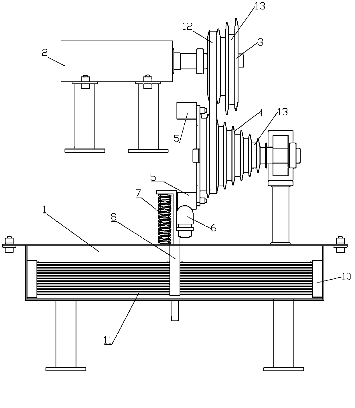
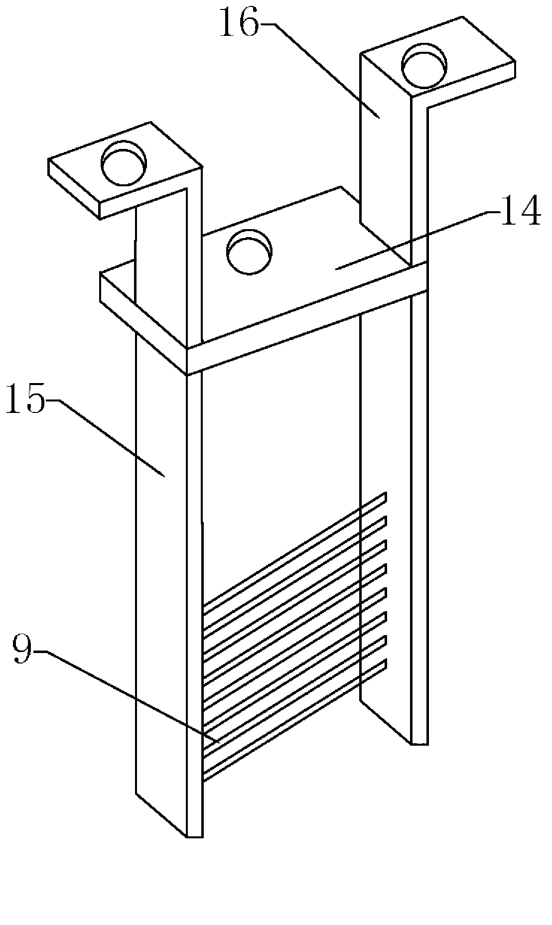
[0024] Example 1: When using, such as figure 1 and figure 2 As shown, the motor 2 drives the driving wheel 3 to rotate, and the driving wheel 3 drives the driven wheel 4 to rotate through the belt 12. Since the diameters of the belt grooves 13 on the driving wheel 3 and the driven wheel 4 have different specifications, it can be adjusted by adjusting the driving wheel. 3 and the matching of the belt groove 13 on the driven wheel 4 controls the driven wheel 4 such as deceleration and acceleration. When the beating rod 5 arranged on the driven wheel 4 contacts the contact 6 fixed on the middle horizontal plate 14 with bolts, it generates a downward force, so that the contact 6 moves downward, and the contact 6 drives the middle grid 8 moves downwards, and the steel bar 9 on the steel bar fixed plate 15 also moves downwards simultaneously, and steel bar 9 exerts force to wire 11. The return spring 7 is fixed on the centering plate 16 of the intermediate network frame 8. When t...
Embodiment 2
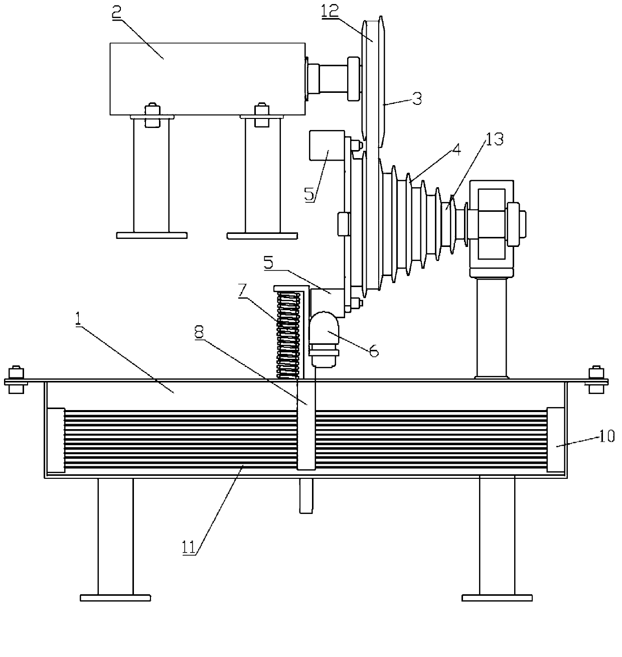
[0025] Example 2: When using, such as figure 2 and image 3 As shown, the motor 2 drives the driving wheel 3 to rotate, and the driving wheel 3 drives the driven wheel 4 to rotate through the belt 12. The driving wheel 3 has only one belt groove 13. By adjusting the position of the driving wheel 3 and the motor 2, it can be matched with different diameters on the driven wheel 4. The belt groove 13 drives the driven wheel 4 to decelerate and accelerate the rotation. When the beating rod 5 arranged on the driven wheel 4 contacts the contact 6 fixed on the middle horizontal plate 14 with bolts, it generates a downward force, so that the contact 6 moves downward, and the contact 6 drives the middle grid 8 moves downwards, and the steel bar 9 on the steel bar fixed plate 15 also moves downwards simultaneously, and steel bar 9 exerts force to wire 11. The return spring 7 is fixed on the centering plate 16 of the intermediate network frame 8. When the beating rod 5 is separated fr...
PUM
 Abstract
Description
Claims
Application Information
 - R&D Engineer
- R&D Manager
- IP Professional
- Industry Leading Data Capabilities
- Powerful AI technology
- Patent DNA Extraction
Browse by: Latest US Patents, China's latest patents, Technical Efficacy Thesaurus, Application Domain, Technology Topic, Popular Technical Reports.
© 2024 PatSnap. All rights reserved.Legal|Privacy policy|Modern Slavery Act Transparency Statement|Sitemap|About US| Contact US: help@patsnap.com