
High-detergency hydraulic oil composition

A technology of hydraulic oil composition and detergency, applied in lubricating compositions, petroleum industry, etc., can solve the problems of rising operating temperature, poor heat transfer effect, affecting valve response speed, etc., and achieve the effect of keeping clean

Active Publication Date: 2013-05-08
CHINA PETROLEUM & CHEM CORP
View PDF2 Cites 8 Cited by
  • Summary
  • Abstract
  • Description
  • Claims
  • Application Information

AI Technical Summary

Problems solved by technology

The sticky valve in the hydraulic system will affect the response speed of the valve and reduce the flow rate of oil
Varnish and sludge also lead to poor heat transfer, higher operating temperatures (sludge, varnish act like insulators) and, moreover, shorten the life of components such as valves, filters, pumps
[0003] Traditional hydraulic oils tend to form paint film or sludge after 500 hours of use. Therefore, it is necessary to develop a hydraulic oil that has the characteristics of traditional hydraulic oils such as anti-wear, anti-corrosion, anti-oxidation, and demulsification. , also has detergency, can reduce the formation of varnish and sludge, and keep the hydraulic system clean

Method used


Image

  • High-detergency hydraulic oil composition
  • High-detergency hydraulic oil composition
  • High-detergency hydraulic oil composition

Examples


Embodiment 1

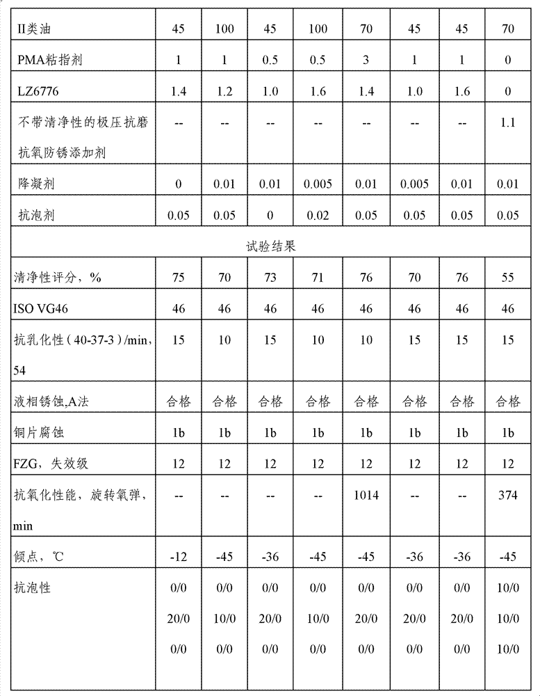
[0032] The components of the hydraulic oil composition in this embodiment are: 55 kg of type I oil, 45 kg of type II oil, 1 kg of PMA viscosity index agent, 1.4 kg of LZ6776, 0.01 kg of pour point depressant, and 0.050 g of antifoaming agent.

[0033] Among them, 150SN is used for type I oil; II4 base oil produced by Shanghai Gaoqiao is used for type II oil; LZ7720C is used for PMA type viscosity index improver; LZ7749B is used for pour point depressant; Produced by Borun Company.

[0034] The preparation process is as follows: mixing each component according to the above ratio, heating to keep the temperature at 45°C, and stirring at the same time, and the stirring time is controlled at 2 hours.

Embodiment 2

[0036] The components of the hydraulic oil composition in this embodiment are: 100 kg of type II oil, 1 kg of PMA viscosity index agent, 1.2 kg of LZ6776, and 0.050 g of antifoaming agent.

[0037] Among them, the II6 base oil produced by Shanghai Gaoqiao was used as the II type oil; the PMA type viscosity index improver was Viscoplex 8-200; the pour point depressant was Empicryl PPT148; the antifoaming agent was 1# composite antifoaming agent.

[0038] The preparation process is as follows: mixing each component according to the above-mentioned ratio, heating to keep the temperature at 50°C, and stirring at the same time, and the stirring time is controlled at 1.5 hours.

Embodiment 3

[0040] The components of the hydraulic oil composition in this embodiment are: 55 kg of type I oil, 45 kg of type II oil, 0.5 kg of PMA viscosity index agent, 1.0 kg of LZ6776, 0.01 kg of pour point depressant, and 0.050 g of antifoaming agent.

[0041] Among them, 500SN is used as the type I oil, and II6 base oil produced by Shanghai Gaoqiao is used as the type II oil; Viscoplex 8-310 is the viscosity index improver of the PMA type; Viscoplex 1-156 is the pour point depressant; foaming agent.

[0042] The preparation process is as follows: mixing each component according to the above-mentioned ratio, heating to keep the temperature at 50°C, and stirring at the same time, and the stirring time is controlled at 1.5 hours.


PUM


Abstract

The invention provides a high-detergency hydraulic oil composition. The composition comprises the following components by weight percent: base oil: 0-55 % of I-class oil and 45-100 % of II-class oil; and additives: 0.1-3 % of a PMA-type viscosity index improver, 1.0-1.6 % of an extreme pressure, clean, anti-wear complex agent, 0-0.01 % of a coagulation reducing agent, and 0-55 ppm of anti-bubble, wherein the amount of the additives is based on the amount of the base oil. The hydraulic oil composition has characteristics of wear resistance, anticorrosion, anti-oxidation and demulsification existing in traditional hydraulic oil, and further has detergency, and can reduce generation of paint film and greasy filth and maintain cleaning of the hydraulic system.

Description

technical field [0001] The invention relates to a lubricating oil composition, in particular to a high-cleaning hydraulic oil composition. Background technique [0002] The development trend of the hydraulic system is that the pressure is getting higher and higher, the fuel tank is getting smaller and smaller, and the power density of the oil is getting higher and higher. Such changes in the hydraulic system bring about an increase in the operating temperature, which in turn leads to oxidation of the hydraulic oil. and thermal degradation to produce products such as sludge or paint film. Over time, the resulting varnish or sludge leads to poor lubricity, increased friction within the valve, and can cause sticking, especially in tight tolerance hydraulic components such as servo valves and proportional valves. The sticky valve in the hydraulic system will affect the response speed of the valve and reduce the flow rate of oil. Varnish and sludge also lead to poor heat transf...

Claims


Application Information

Patent Timeline
IPC IPC(8): C10M169/04C10N40/08C10N30/04
Inventor 陈惠卿汤涛李万英王向阳刘继勇韦安柱贾睿薛玉苓艾立雯水琳
Owner CHINA PETROLEUM & CHEM CORP
Learn More