Eureka AIR delivers breakthrough ideas for toughest innovation challenges, trusted by R&D personnel around the world.

Liquid crystal display device

一种液晶显示装置、液晶的技术,应用在静态指示器、光学、仪器等方向,能够解决光偏转器偏转速度下降、液晶面板图像画质下降、不能快速地切换等问题,达到扩大偏转角度的效果

Inactive Publication Date: 2013-05-01
PANASONIC CORP
View PDF8 Cites 5 Cited by
  • Summary
  • Abstract
  • Description
  • Claims
  • Application Information

AI Technical Summary

Problems solved by technology

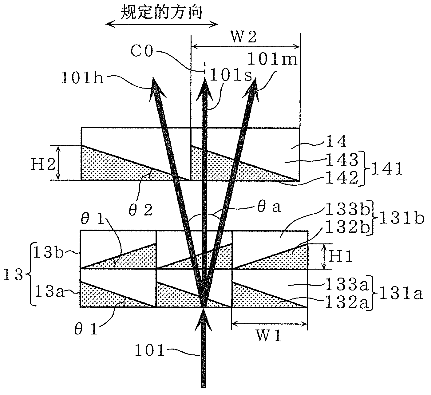
[0010] In the above-mentioned conventional liquid crystal display device, in order to increase the deflection angle of light in the light deflector, the height of the liquid crystal constituting the light deflector (that is, the height in the direction from the light incident side to the light exit side) When it becomes relatively large, it causes the light deflection speed of the light deflector to decrease
When the light deflection speed of the light deflector decreases, the display of the image for the right eye and the display of the image for the left eye cannot be quickly switched, resulting in a problem that the quality of the image displayed on the liquid crystal panel deteriorates.

Method used


Image

  • Liquid crystal display device
  • Liquid crystal display device
  • Liquid crystal display device

Examples


Embodiment 1

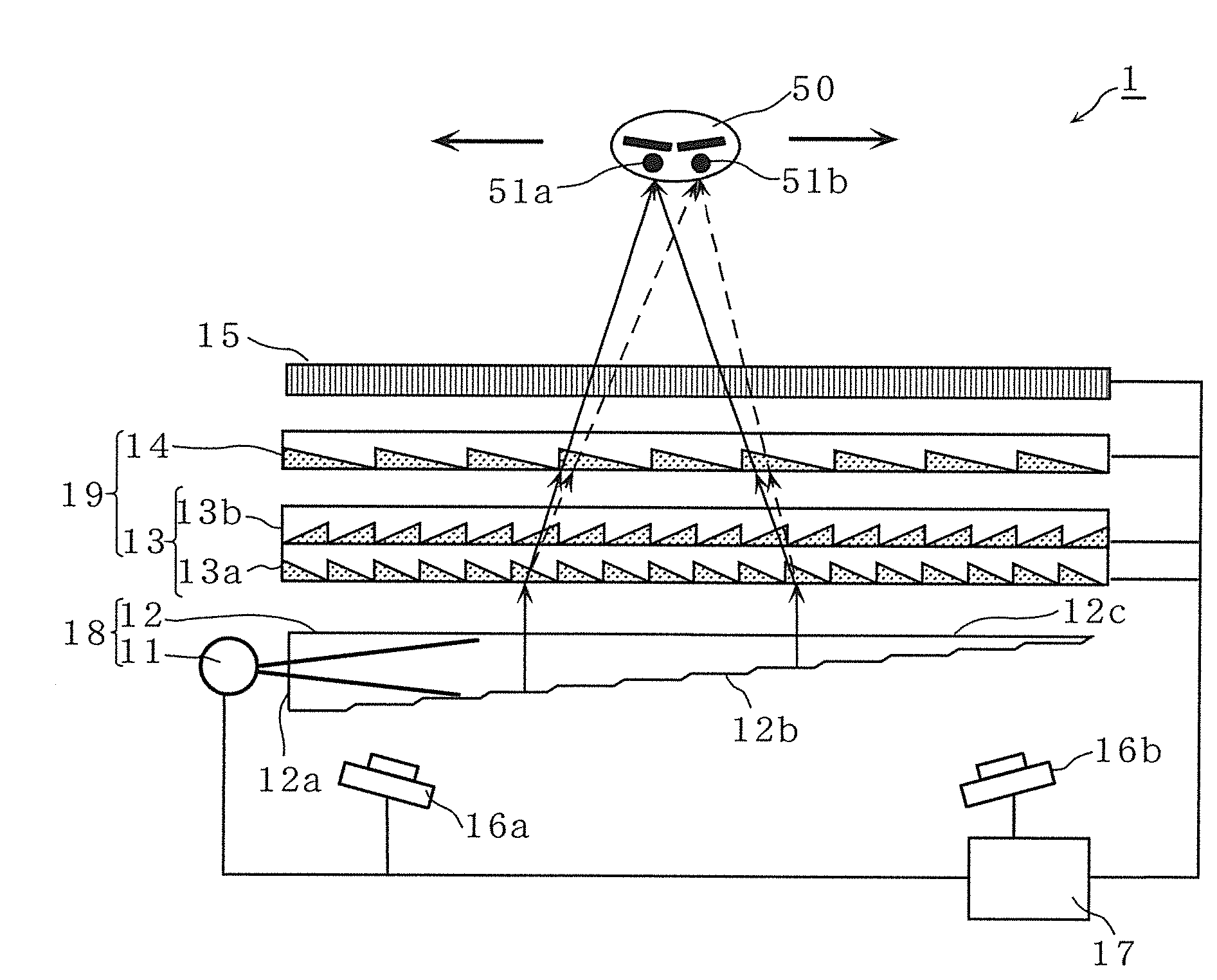
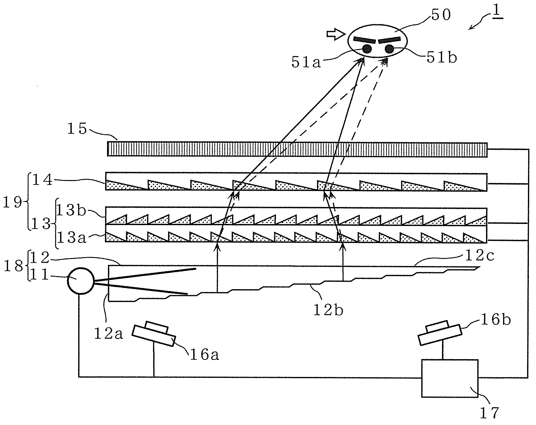
[0071] Figure 1A , Figure 1BIt is a cross-sectional view showing the liquid crystal display device 1 according to Example 1 of the present invention. The illustrated liquid crystal display device 1 includes a light source 11, a light guide plate 12, a first light deflector 13, a second light deflector 14, a liquid crystal panel 15, a pair of stereo cameras 16a, 16b (constituting a head position detection unit and a binocular position detection unit). detection unit) and the control unit 17. The liquid crystal display device 1 of this embodiment is, for example, a flat-panel three-dimensional display capable of viewing three-dimensional images with naked eyes without wearing special glasses.

[0072] The light source 11 is composed of, for example, a plurality of light emitting diodes (Light Emitting Diodes). Figure 1A Arrange the settings in the vertical direction of the paper surface. The light source 11 radiates light toward a side surface 12 a of the light guide plate ...

Embodiment 2

[0118] Figure 5 It is a cross-sectional view showing a liquid crystal display device 1A according to Example 2 of the present invention. In addition, in each of the following examples, the same components as those of the above-mentioned example 1 are denoted by the same reference numerals, and description thereof will be omitted.

[0119] The illustrated liquid crystal display device 1A includes a polarizing reflection film 21 , a quarter-wave plate 22 , and a reflection sheet 23 in addition to the components of the liquid crystal display device 1 of the first embodiment.

[0120] The polarizing reflective film 21 is disposed between the first light deflector 13 and the second light deflector 14 . The polarizing reflective film 21 is a film having properties such that the first polarization direction (for example, with respect to Figure 5 of the paper is the light reflection in the vertical direction), and, so that the second polarization direction is orthogonal to the fir...

Embodiment 3

[0128] Figure 6 It is a cross-sectional view showing a liquid crystal display device 1B according to Example 3 of the present invention. In the liquid crystal display device 1B of this embodiment, the polarizing reflection film 21 is provided between the second light deflector 14 and the liquid crystal panel 15 . The other configurations of the liquid crystal display device 1B are the same as those of the second embodiment.

[0129] In this embodiment, the light emitted from the main surface 12 c of the light guide plate 12 passes through the first light deflector 13 and the second light deflector 14 three times. In this way, the deflection angle of the light by the first light deflector 13 can be tripled compared to the case where the light passes through the first light deflector 13 only once. In addition, compared with the case where the light passes through the second light deflector 14 only once, the deflection angle of the light by the second light deflector 14 can be...


PUM


Abstract

This liquid crystal display device is provided with: a light irradiation unit (18) which emits light; a light deflector (19), which deflects the light emitted from the light irradiation unit (18); a control unit (17), which controls light deflection angle of the light deflector (19); and a liquid crystal panel (15), which forms an image by means of light outputted from the light deflector (19). The light deflector (19) is configured of a first light deflector (13) and a second light deflector (14), which are disposed by being aligned in the direction from the light input side toward the light output side. A maximum light deflection angle of the first light deflector (13) is smaller than a maximum light deflection angle of the second light deflector (14), and a maximum light deflection speed of the first light deflector (13) is higher than a maximum light deflection speed of the second light deflector (14). The first light deflector (13) is configured by laminating a first light deflection layer (13a) and a second light deflection layer (13b) in the direction from the light input side toward the light output side, said first light deflection layer and second light deflection layer respectively having a plurality of liquid crystal deflection elements planarly disposed therein.

Description

technical field [0001] The present invention relates to a liquid crystal display device using a light deflector capable of freely deflecting light. Background technique [0002] Various studies have been conducted on light deflectors that deflect incident light. For example, a light deflector is an indispensable device for a laser scanner used in a laser printer or the like. Conventionally, polygon mirror scanners, galvanometer scanners, MEMS (Micro Electro Mechanical System) mirrors, and the like have been used as light deflectors, for example. However, since such polygon mirror scanners, galvanometer scanners, and MEMS mirrors are provided with movable parts (mechanical mechanisms) for moving parts, failures are prone to occur. Therefore, the development of an optical deflector capable of deflecting light without providing a movable part has been expected. [0003] In response to this demand, an optical deflector as disclosed in Patent Document 1 below has been develope...

Claims


Application Information

Patent Timeline
Patent Type & Authority Applications(China)
IPC IPC(8): G02F1/13G02F1/133G02F1/1347G02B30/28
CPCH04N13/04G02F1/1313G02F1/133615G02F1/29G02F1/1347G02F1/13G02F1/133G02B27/0093H04N13/312H04N13/32H04N13/371H04N13/373H04N13/376G02B30/36G02B30/28
Inventor 杉山圭司式井慎一
Owner PANASONIC CORP
Why Eureka
Eureka Blog
Learn More