A steel pallet support force transmission system

A force transmission system and pallet technology, applied in pillars, building maintenance, infrastructure engineering, etc., can solve problems such as uneven support force, affect construction, and take up space, achieve strong support stability, reduce construction costs, and take up space. less effect

Active Publication Date: 2016-01-13
GUANGZHOU SHENGTE BUILDING TECH DEVCO
View PDF13 Cites 0 Cited by
  • Summary
  • Abstract
  • Description
  • Claims
  • Application Information

AI Technical Summary

Problems solved by technology

This method of new reinforced concrete column support takes a long time and increases the point load. It is not recommended to use this method in actual engineering; Uniform support force creates potential safety hazards and takes up a lot of space, affecting construction
[0003] The above traditional technical solutions have limitations in actual construction. For example, when it is necessary to replace the hidden corner columns, due to the influence of the space position, it is impossible to add reinforced concrete columns or steel supports, so the replacement cannot be completed. In serious cases, the building needs to be replaced. Things need to be dismantled and rebuilt, which makes the cost of entrustment larger

Method used


Image

  • A steel pallet support force transmission system
  • A steel pallet support force transmission system
  • A steel pallet support force transmission system

Examples


Embodiment 1

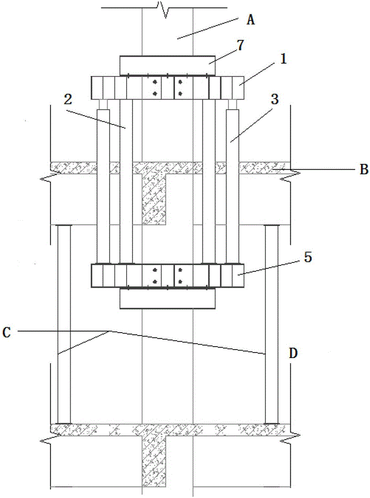
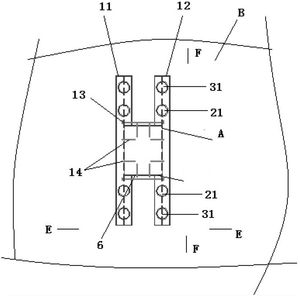
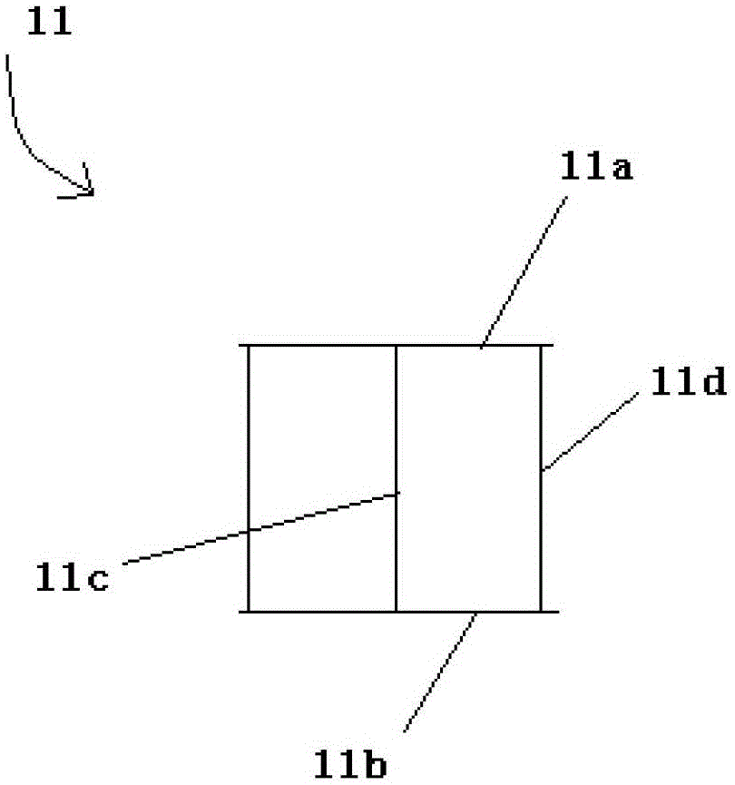
[0028] see Figure 1~Figure 5 , the steel tray support force transmission system of this embodiment includes an upper steel tray assembly 1, a main support assembly 2, an auxiliary support assembly 3, a jack 4, and a lower steel tray assembly 5; wherein, the upper steel tray assembly is located on the floor B, and the lower The steel tray assembly is located between the floors B and D, the main support assembly and the auxiliary support assembly pass through the floor B; a joint support system C is provided between the floor B and the floor D; the upper steel tray assembly 1 includes horizontally arranged along its length The first steel beam 11 and the second steel beam 12 on the opposite sides of the underpinned or replaced column A, the lower steel tray assembly 5 includes horizontally arranged on the opposite sides of the underpinned or replaced column along its length direction The third steel beam 51 and the fourth steel beam 52, wherein the structures of the first steel...

Embodiment 2

[0043] see Figure 6 ~ Figure 8 , the steel tray supporting force transmission system of this embodiment is used for shear wall underpinning, and it includes an upper steel tray assembly 1 and a lower steel tray assembly 5, and a main support assembly arranged between the upper steel tray assembly and the lower steel tray assembly 2 and auxiliary support assembly 3. Wherein, the upper steel tray assembly 1 is located on the floor H above the shear wall G to be underpinned, and the lower steel tray assembly 5 is located on the floor I below the shear wall G to be underpinned; the upper steel tray assembly 1 includes several intervals. The upper steel beam 1a, the lower steel tray assembly 5 includes a plurality of lower steel beams 5a arranged at intervals, the upper steel beam 1a in the upper steel tray assembly is set in one-to-one correspondence with the number and position of the lower steel beams in the lower steel tray assembly 5; and The structure and size of the upper ...


PUM


Abstract

The invention discloses a steel tray supporting force transferring system, which comprises an upper steel tray assembly, a lower steel tray assembly and support assemblies, wherein the upper steel tray assembly is used for bearing a load above a target building member; the lower steel tray assembly is used for transferring the load above the target building member to a lower building; the support assemblies are arranged between the upper steel tray assembly and the lower steel tray assembly, and are used for transferring the load above the target building member borne by the upper steel tray assembly to the lower steel tray assembly; the upper steel ray assembly comprises a plurality of upper steel beams; the lower steel tray assembly is correspondingly provided with a plurality of lower steel beams one by one; and the upper steel beams and the lower steel beams are I-shaped steel beams or channel steel beams or combined steel beams. The steel tray supporting force transferring system has the advantages of convenience in underpinning, replacing or lifting and rectifying the target building member, high supporting stability, safety, reliability, low space occupation, convenience in installing and using, flexible selection of underpinned components, detachability for repeated use, and reduction in the construction cost.

Description

technical field [0001] The invention relates to the technical field of building underpinning / replacement, in particular to a steel pallet supporting force transmission system. Background technique [0002] When a column or shear wall concrete needs to be replaced, the traditional method in the prior art is to build a new reinforced concrete column support next to the column or shear wall that needs to be underpinned or replaced, or to use a large area of ​​steel pipe support. This method of new reinforced concrete column support takes a long time and increases the point load. It is not recommended to use this method in actual engineering; Uniform support force creates potential safety hazards and takes up a lot of space, affecting construction. [0003] The above traditional technical solutions have limitations in actual construction. For example, when it is necessary to replace the hidden corner columns, due to the influence of the space position, it is impossible to add r...

Claims


Application Information

Patent Timeline
Patent Type & Authority Patents(China)
IPC IPC(8): E04G23/02E04G23/06E04G25/04E02D35/00
Inventor 吴如军唐颖曾春航赵正兴胡前丽
Owner GUANGZHOU SHENGTE BUILDING TECH DEVCO
Why Eureka
Try Eureka