Brake control method of electric tool

A brake control and electric tool technology, applied in the electric tool brake (commonly known as brake) control, electric tool control field, can solve the field effect tube heating, shorten the service life of the device, start and stop, frequent reversing operations, etc.

Active Publication Date: 2015-07-01
NANJING JIUCHI ELECTROMECHANICAL IND
View PDF6 Cites 0 Cited by
  • Summary
  • Abstract
  • Description
  • Claims
  • Application Information

AI Technical Summary

Problems solved by technology

[0004] In practice, the applicant found that since the start-stop and reversing operations are very frequent when the electric tool is used, the microprocessor only simply outputs the continuous braking control signal. When the ambient temperature is high, it is not only easy to affect the braking effect due to the instability of the device, but also significantly shorten the service life of the device

Method used


Image

  • Brake control method of electric tool
  • Brake control method of electric tool
  • Brake control method of electric tool

Examples


Embodiment 1

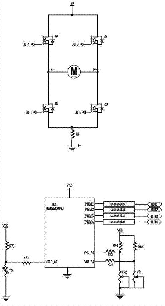
[0023] The power tool in this embodiment is an electric drill (see 201210262057.x), which contains figure 1 In the circuit shown, the positive pole B+ of the power supply passes through the forward-rotating front-end field effect transistor Q3, passes through the positive pole M+ of the motor to the negative pole M-, and then connects the forward-rotating rear field effect transistor Q1 to the negative pole B- of the power supply to form a forward-rotating drive circuit. The positive pole B+ passes through the reverse front field effect transistor Q4, passes through the negative pole M- of the motor to the positive pole M+, and then connects the reverse field effect transistor Q2 to the negative pole B- of the power supply to form a reverse drive circuit. The controlled terminals PWM1-PWM4 of each FET are respectively connected to the driving output terminals of the corresponding control signals of the microprocessor U3 in the control circuit. The two switch signal input termi...


PUM


Abstract

The invention relates to a brake control method of an electric tool, which belongs to the technical field of the electric tool. The method is characterized in that a positive electrode of a power supply respectively passes through a forward and a backward front front-mounted field effect tubes to be led into a drive circuit of a negative electrode of the power supply through a motor and a corresponding forward and backward back-mounted field effect tubes, a controlled end of each field effect tube is respectively connected with the drive output end of a microprocessor, two switch signal input ends of the microprocessor are respectively connected with a forward-backward control signal output end of a switch assembly, and a temperature signal input end of the microprocessor is connected with a temperature signal output end of a temperature sensor which is arranged nearby the field effect tubes. A reasonable brake mode is selected according to the temperature of the field effect tubes, when the temperature is too high, the electric tool is rapidly powered off and stopped; when the temperature is high, brake is applied in a relative long time interval; when the temperature is slightly high, the brake is applied in a relative short time interval; and when the temperature is not high, the brake is applied continuously. Therefore, the temperature increase in the brake of the field effect tubes can be effectively controlled, so that the brake performance of the electric tool is stable and reliable, and the service life of the electric tool can be prolonged.

Description

technical field [0001] The invention relates to a control method for an electric tool, in particular to a control method for braking (commonly known as braking) of an electric tool, and belongs to the technical field of electric tools. Background technique [0002] When electric tools such as electric hand drills are used, they need to go through a braking process when starting, stopping, and reversing operations. The Chinese invention patent application with the application number 201210262057.x discloses "A Speed ​​Control Device and Control Method for Electric Tools". When the forward and reverse control of the invention is required, only the fingers of the two corresponding buttons need to apply force respectively. When the speed needs to be adjusted, it is very convenient to control the strength with the finger that is added to the force, and there is no need to change the holding posture during the entire operation process, so safety can be ensured. [0003] The motor...

Claims


Application Information

Patent Timeline
IPC IPC(8): B25F5/00H02H7/08
Inventor 卢志学
Owner NANJING JIUCHI ELECTROMECHANICAL IND
Why Eureka
Try Eureka