Disc type brake device structure in robot joint module

A technology for robot joints and braking devices, which is applied to manipulators, manufacturing tools, etc., can solve the problems of high brake cost, low braking precision, and small torque, and achieve the effect of low component cost and stable and reliable braking performance.

Pending Publication Date: 2019-01-29
上海宇塚电子科技有限公司
View PDF0 Cites 4 Cited by
  • Summary
  • Abstract
  • Description
  • Claims
  • Application Information

AI Technical Summary

Problems solved by technology

However, there are many obvious defects in the solenoid valve: the current is high during the electrification process, which easily causes the product to heat up; the specification of the solenoid valve is small, and it needs to be reprocessed to meet the requirements of use; the reliability and life of the parts are low; the structural strength is low, and the valve head is constantly impacted. easy to damage; the installation structure is relatively complicated; the torque generated by the coil is small, and there is a risk of braking failure; the braking accuracy is low
[0004] Two kinds of brakes are currently used: one is disc brakes provided for brake manufacturers, but this kind of brakes often cannot find suitable specifications (the use of hollow shafts in joint modules requires corresponding large inner holes, small outer diameters, flat and thin types) brake), and the cost of this brake is too high; the other uses a DC solenoid valve as a substitute, which maintains an adsorption state when electrified, and pops up the valve head to block the rotation of the motor shaft when the power is off, acting as a brake
However, there are many defects in this solution: the current is high during the electrification process, which is easy to cause the product to heat up; the solenoid valve has fewer specifications and needs to be reprocessed to meet the use requirements; the reliability and life of the parts are low; the structural strength is low, and when the valve head is constantly impacted Easy to damage; the installation structure is relatively complicated; the torque generated by the coil is small, there is a risk of braking failure, and the braking accuracy is low

Method used


Image

  • Disc type brake device structure in robot joint module
  • Disc type brake device structure in robot joint module

Examples


Embodiment Construction

[0018] In order to make the present invention more comprehensible, preferred embodiments are described in detail below with accompanying drawings.

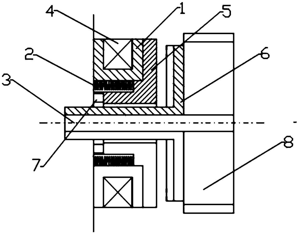
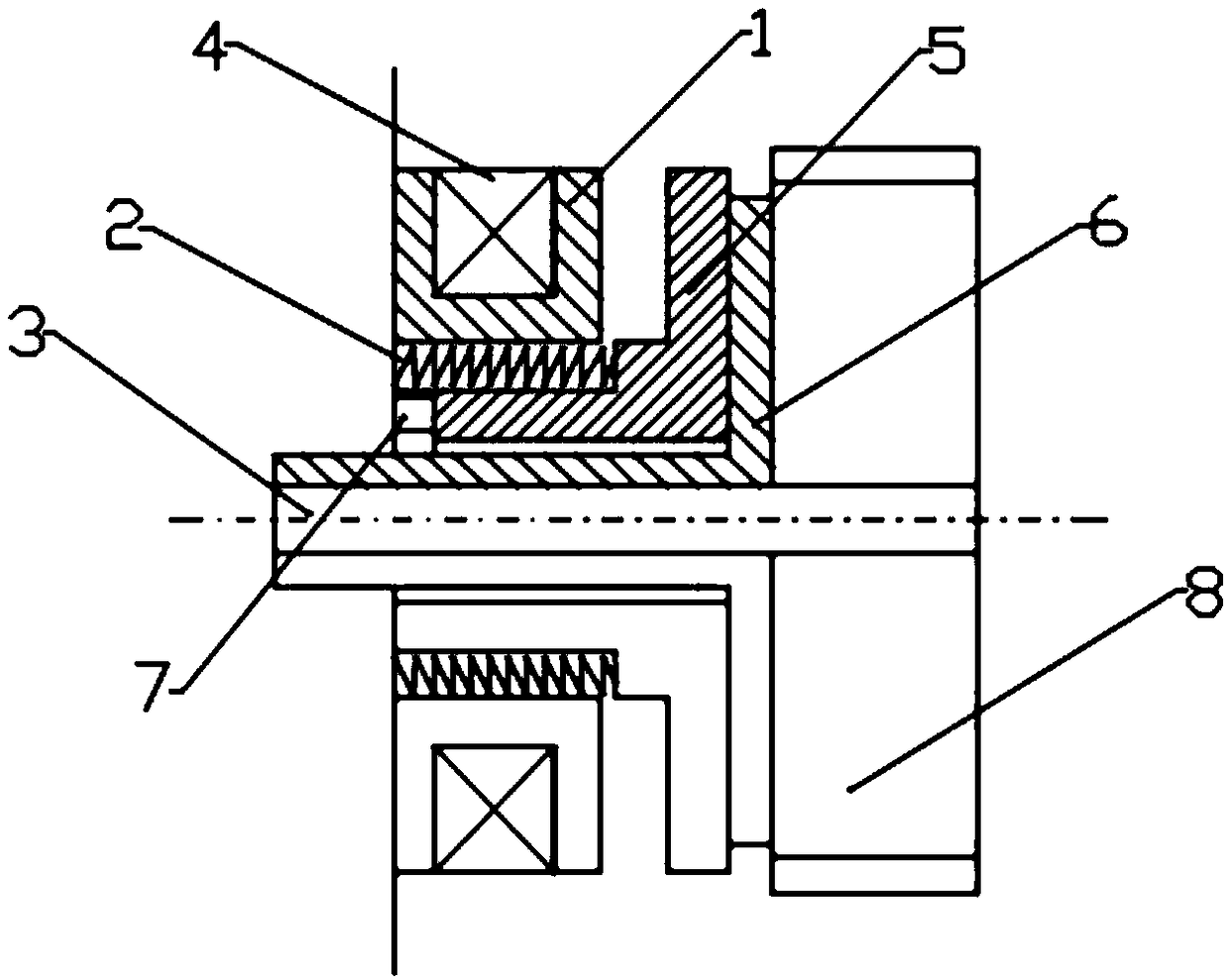
[0019] Such as Figure 1 to Figure 2 As shown, in order to use the traditional power-off brake to produce the braking effect by utilizing the mechanical action of the coil to be adsorbed on the spring, a disc brake device structure in the robot joint module is designed, which includes the motor rotor 8 Hollow motor shaft 3, one side of the motor rotor 8 is provided with a brake groove 6 sleeved on the hollow motor shaft 3, and the brake groove 6 includes a restricting shaft sleeved outside the hollow motor shaft 3 and arranged on The restriction surface on one side of the motor rotor 8, the restriction shaft of the braking groove 6 is provided with a sliding braking component 5, and the sliding braking component 5 includes a sliding shaft and a vertical On the sliding restriction surface of the sliding shaft, the sliding restrict...


PUM


Abstract

The invention discloses a disc type brake device structure in a robot joint module. The disc type brake device structure comprises a hollow motor shaft arranged in a rotor of a motor in a sleeved mode, and a brake groove formed in the hollow motor shaft in a sleeving mode is formed in one side of the rotor of the motor. The brake groove includes a restriction shaft arranged outside the hollow motor shaft in a sleeving mode and a restriction surface disposed on one side of the rotor of the motor, and a sliding brake member is disposed on the restriction shaft of the brake groove. The sliding brake member includes a sliding shaft arranged outside the restriction shaft of the brake groove in a sleeving mode and a sliding restriction surface perpendicular to the sliding shaft. The sliding restriction surface on the sliding brake member is absorbed on one side of an energizing coil through an iron core disposed in the energizing coil, and a power-down brake spring is disposed under the coil. After the power-down brake spring is popped out, the sliding restriction surface of the sliding brake member is pushed to the restriction surface of the brake groove. The overall disc type brake device structure is a rotating body, the braking performance is more stable and reliable during operation, the structure of multi-groove braking reduces the influence caused by impact, and the parts costof the structure is low.

Description

technical field [0001] Robot collaboration, hollow motor, servo motor, high-precision motor The present invention relates to a robot joint module, in particular to a structure of a disc brake device in a robot joint module. Background technique [0002] In the course of the blowout development of the robot industry, a series of supporting facilities such as joint modules with small size and simple assembly methods have also developed accordingly. Then the corresponding brake industry currently focuses on traditional servo motors and other industries, and has not yet targeted small external parts. Hollow shaft joints with large diameter and large inner diameter provide a matching brake solution. [0003] The brake is an indispensable part of the joint module. It is often difficult to find a suitable size (including outer diameter, inner hole size, thickness, and quality) for the brakes on the market. In addition, the cost is too high, and it is difficult to match the specific...

Claims


Application Information

Patent Timeline
Patent Type & Authority Applications(China)
IPC IPC(8): B25J19/00
CPCB25J19/0004
Inventor 田井海鸣戴洋周文杰
Owner 上海宇塚电子科技有限公司
Why Eureka
Try Eureka