Two leading shoe type brake

A technology of brakes and leading shoes, applied in the direction of drum brakes, brake types, brake parts, etc., can solve the problems of increased braking force, unbalanced braking force, poor braking effect, etc., and achieve the effect of convenient disassembly

Inactive Publication Date: 2016-02-03
CHONGQING YUANCHUANG WHOLE LINE INTEGRATION
View PDF14 Cites 0 Cited by
  • Summary
  • Abstract
  • Description
  • Claims
  • Application Information

AI Technical Summary

Problems solved by technology

[0003] Drum brakes use brake shoes to squeeze brake wheels to obtain braking force. Traditional drum brakes use one brake wheel cylinder to drive two brake shoes at the same time. This driving method can only make one brake shoe brake When the rotation direction of the brake shoe is the same as that of the brake wheel, the rotation direction of the other brake shoe will be opposite to that of the brake wheel. When the rotation direction of the brake shoe and the brake wheel is the same, the brake shoe and the brake The tangential reaction force between the wheels will increase the pressing force between the brake shoe and the brake wheel, thereby increasing the braking force between the two. When the brake shoe and the brake wheel rotate in the opposite direction , the tangential reaction force between the brake shoe and the brake wheel reduces the braking force between the two, so the brake with this structure will cause the braking force of the two brake shoes on the brake wheel to be unbalanced, and at the same time the two The degree of wear of the brake shoes will also be different, which will make the braking performance of the entire brake unstable and the braking effect poor

Method used


Image

  • Two leading shoe type brake

Examples


Embodiment Construction

[0012] The present invention will be described in further detail below by means of specific embodiments:

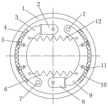
[0013] The reference signs in the drawings of the description include: brake wheel 1, first brake wheel cylinder 2, first brake shoe 3, first friction plate 4, first groove 5, first tension spring 6, pin shaft 7. The second brake wheel cylinder 8, the second brake shoe 9, the second friction plate 10, the second groove 11, and the second tension spring 12.

[0014] The embodiment is basically as attached figure 1 Shown: double-collar shoe brake, including brake wheel 1, brake wheel 1 is an internal hollow structure, on the upper side of the hollow structure of brake wheel 1, there is a first brake wheel cylinder 2, the first brake wheel cylinder 2. It is fixedly connected with the external frame through the threaded hole on the right side. The first brake shoe 3 is provided on the left side of the first brake wheel cylinder 2. The first brake shoe 3 is a crescent-shaped ...


PUM


Abstract

The invention discloses a two leading shoe type brake. The two leading shoe type brake comprises a brake wheel, wherein a first brake shoe and a second brake shoe are correspondingly arranged at two sides of the inner wall of the brake wheel; one side of the first brake shoe is hinged with an external rack while the other side of the first brake shoe is provided with a first brake wheel cylinder; the second brake shoe is positioned at one side of the first brake wheel cylinder and is hinged with the external rack; a second brake wheel cylinder is arranged at the other side of the second brake shoe; a first tension spring and a second tension spring are arranged between the first brake shoe and the second brake shoe. The two leading shoe type brake has the beneficial effects that the two brake shoes can be correspondingly matched with pistons of two different brake wheel cylinders to perform braking, so that the rotating directions of the two brake shoes in an opening state are the same as the rotating directions of the brake wheels, and as a result, the brake effect can be improved, and moreover, the abrasion uniformity of the whole brake shoes can be ensued, and the braking performance of the whole brake is stable and reliable.

Description

technical field [0001] The invention relates to a drum brake, in particular to a double collar shoe brake. Background technique [0002] The brake is a component in the braking system that is used to generate the force that hinders the movement or movement tendency of the vehicle. Except for various slowing devices, the automobile brakes are almost all friction brakes that use the friction between the fixed element and the working surface of the rotating element to generate braking torque. , At present, the friction brakes widely used in various types of automobiles are divided into two categories: drum brakes and disc brakes according to the different rotating elements. [0003] Drum brakes use brake shoes to squeeze brake wheels to obtain braking force. Traditional drum brakes use one brake wheel cylinder to drive two brake shoes at the same time. This driving method can only make one brake shoe brake When the rotation direction of the brake shoe is the same as that of th...

Claims


Application Information

Patent Timeline
IPC IPC(8): F16D51/18F16D65/09F16D65/14F16D69/04F16D121/04
Inventor 陈振丰
Owner CHONGQING YUANCHUANG WHOLE LINE INTEGRATION
Why Eureka
Try Eureka