Light emitting device, illuminating system, and illuminating method

A light-emitting device and lighting system technology, applied in the direction of lighting devices, electroluminescent light sources, lighting and heating equipment, etc., can solve the problem of complex calculation steps of driving current

Inactive Publication Date: 2013-04-24
MITSUBISHI CHEM CORP
View PDF11 Cites 23 Cited by
  • Summary
  • Abstract
  • Description
  • Claims
  • Application Information

AI Technical Summary

Problems solved by technology

[0019] In the light-emitting device disclosed in Patent Document 3, all the light-emitting sources emit light over the entire range of dimming levels, so there is a problem that the light emitted from a plurality of light-emitting sources needs to be considered over the entire range of dimming levels. In order to obtain white light with the desired color temperature, the calculation steps of the driving current provided to each light source are always very complicated

Method used


Image

  • Light emitting device, illuminating system, and illuminating method
  • Light emitting device, illuminating system, and illuminating method
  • Light emitting device, illuminating system, and illuminating method

Examples


no. 1 Embodiment

[0161] (Structure of light emitting part)

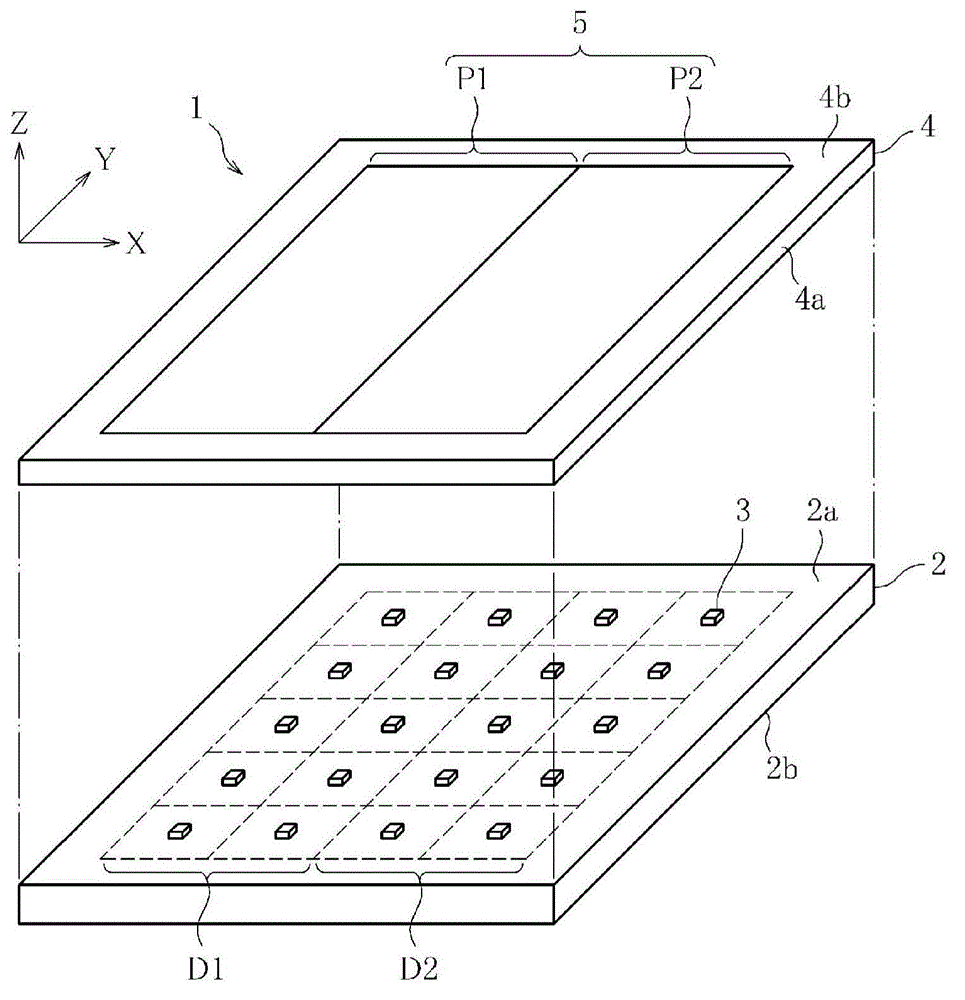
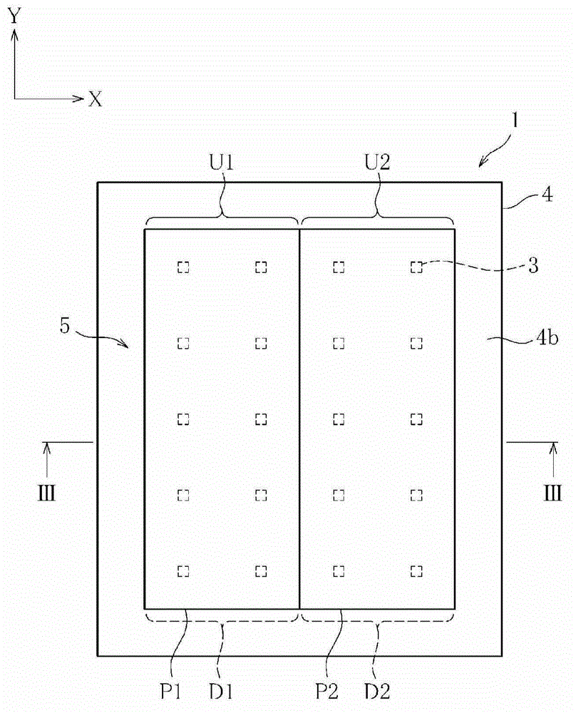
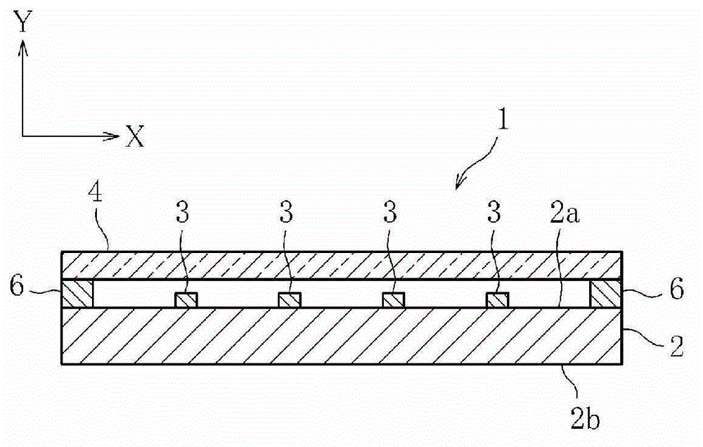
[0162] figure 1 It is a perspective view schematically showing the overall structure of the light emitting unit 1 in the light emitting device (illumination device) of this embodiment, figure 2 yes figure 1 The top view of the light-emitting part 1. In addition, in figure 1 and figure 2 In , the width direction of the light emitting part 1 is defined as the X direction, the length direction is defined as the Y direction, and the height direction is defined as the Z direction. Such as figure 1 As shown, the light emitting unit 1 includes a wiring board 2 made of alumina-based ceramics that is excellent in electrical insulation and has good heat dissipation. On the chip mounting surface 2a of the wiring substrate 2, four chips are arranged at equal intervals in the width direction of the wiring substrate 2 (that is, the X direction), and five chips are arranged at equal intervals in the longitudinal direction (that is, the Y di...

no. 2 Embodiment >

[0257] In the first embodiment described above, the fluorescent member 5 is constituted by the first wavelength conversion region P1 and the second wavelength conversion region P2 that emit primary light having different color temperatures. That is, two types of primary light having different color temperatures are emitted from the fluorescent member 5 . However, various changes and substitutions can be made without departing from the gist of the present invention. Therefore, hereinafter, as a second embodiment of the present invention, a light emitting unit 1', a light emitting device 11', and a lighting system using a fluorescent member 5' having a structure different from that of the fluorescent member 5 of the first embodiment will be described. A case of 12'. In addition, the same reference numerals are assigned to the same components and structural parts as those of the first embodiment, and their descriptions are omitted.

[0258] (Structure of light emitting part)

...

no. 3 Embodiment >

[0304] In the first embodiment described above, the fluorescent member 5 is constituted by the first wavelength conversion region P1 and the second wavelength conversion region P2 that emit primary light having different color temperatures. That is, two types of primary light having different color temperatures are emitted from the fluorescent member 5 . However, various changes and substitutions can be made without departing from the gist of the present invention. Therefore, in the following, as a third embodiment of the present invention, a light emitting unit 1", a light emitting device 11" and a lighting system using a fluorescent member 5" having a structure different from that of the fluorescent member 5 of the first embodiment will be described. 12" example. In addition, the same reference numerals are assigned to the same components and structural parts as those of the first embodiment, and their descriptions are omitted.

[0305] (Structure of light emitting part) ...


PUM


Abstract

Provided is a light emitting device which has: a plurality of LED chips (3), which are disposed on the LED chip mounting surface of a wiring board (2), and are grouped into a plurality of LED groups,a wavelength conversion member (5), which is disposed at a position that corresponds to the LED chip mounting surface, converts the wavelength of light emitted from the corresponding LED chips (3), and emits primary light having color temperatures different from each other by wavelength conversion region,a current supply unit (15), which separately supplies drive currents to the LED chips (3) by each LED group via the wiring board (2),and a control unit (16), which controls the quantity of a current to be supplied to each LED group corresponding to control signals inputted from the outside. The control unit (16) can suppress unsuitable luminous flux reduction at the time of adjusting the color temperatures, while ensuring excellent color rendering characteristics, by independently controlling, corresponding to dimming levels, lighting start times of the LED groups, and the control unit makes it possible to obtain light having a color temperature suitable for a desired light emission intensity by controlling the light emission intensity and the color temperatures. Also provided are an illuminating system using the light emitting device, and an illuminating method.

Description

technical field [0001] The present invention relates to a light-emitting device using an LED chip that emits light in a predetermined wavelength range between the visible light region and the near-ultraviolet region, and a wavelength converting member that converts the wavelength of the light emitted by the LED chip, and an illumination system using the light-emitting device , and an illumination method for converting wavelengths of light emitted from a plurality of LED chips by a wavelength conversion member and combining them to form desired combined light. Background technique [0002] Conventionally, incandescent bulbs and fluorescent lamps have been widely used as light sources for lighting devices. In recent years, other than these, light-emitting devices using semiconductor light-emitting elements such as light-emitting diodes (LED: Light Emitting Diode) and organic EL (OLED) as light sources have been developed and used. Various light-emitting colors can be obtained...

Claims


Application Information

Patent Timeline
Patent Type & Authority Applications(China)
IPC IPC(8): F21S2/00F21S10/00F21Y101/02H05B44/00F21V9/40
CPCF21Y2105/003H01L24/97H05B33/0863H01L25/0753H01L33/504F21K9/56H05B33/0857H01L33/50H01L2224/16225F21Y2101/02F21V9/16H01L2924/01322H01L2924/12041H01L2924/1301H01L2924/13033H01L2224/73265H01L2224/48091H01L2924/15747H01L2924/12044H01L2924/181F21Y2105/12F21Y2105/10F21K9/64F21Y2115/10H05B45/20F21V9/32F21V9/38F21V13/08H01L2924/00H01L2924/00014H01L2924/00012
Inventor 树神弘也木岛直人武田立服部英次胜本觉成横尾敏明与安史子小岛隆
Owner MITSUBISHI CHEM CORP
Why Eureka
Try Eureka