Approximate exposure device, method for positioning substrate of approximate exposure device, and method for manufacturing substrate of display panel

A technology of exposure device and positioning method, which is applied in the direction of exposure device of photo-plate making process, photo-plate-making process of pattern surface, micro-lithography exposure equipment, etc., can solve the problem of increased cost of photomask, and achieve the effect of good precision

Inactive Publication Date: 2013-04-24
HITACHI HIGH-TECH CORP
View PDF7 Cites 5 Cited by
  • Summary
  • Abstract
  • Description
  • Claims
  • Application Information

AI Technical Summary

Problems solved by technology

At this time, for the approach method, if one side of the substrate is to be uniformly exposed, a photomask of the same size as the substrate is required, which further increases the cost of expensive photomasks.

Method used


Image

  • Approximate exposure device, method for positioning substrate of approximate exposure device, and method for manufacturing substrate of display panel
  • Approximate exposure device, method for positioning substrate of approximate exposure device, and method for manufacturing substrate of display panel
  • Approximate exposure device, method for positioning substrate of approximate exposure device, and method for manufacturing substrate of display panel

Examples


Embodiment Construction

[0086] In order to further illustrate the technical means and effects that the present invention adopts to achieve the intended invention purpose, below in conjunction with the accompanying drawings and preferred embodiments, the approach exposure device proposed according to the present invention, its substrate positioning method and the production of the panel substrate for display will be described. Its specific implementation, structure, method, steps, features and effects thereof are described in detail below.

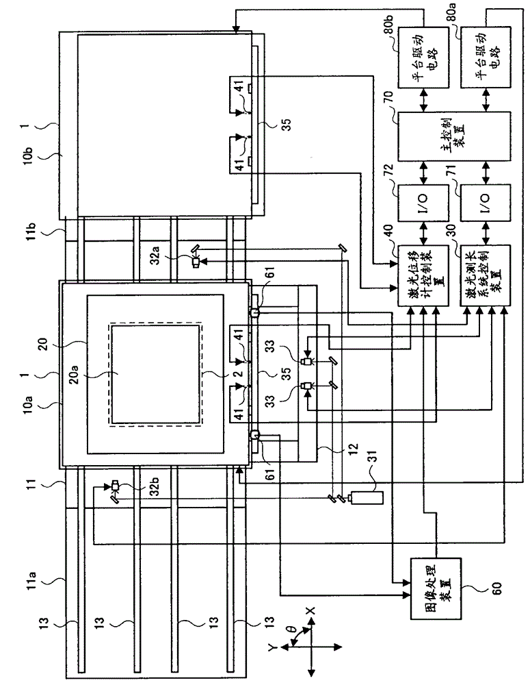
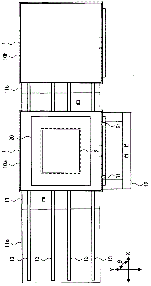
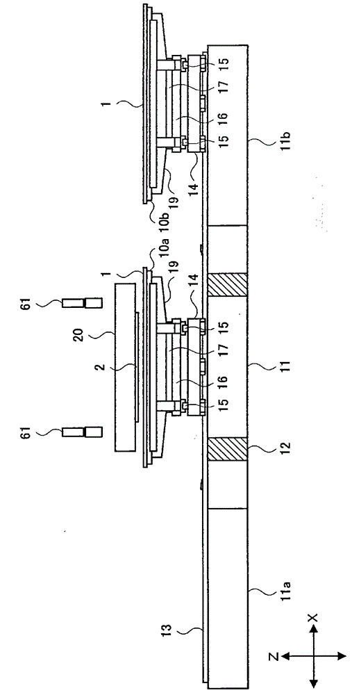
[0087] figure 1 It is a figure which shows the schematic structure of the proximity exposure apparatus which concerns on one Embodiment of this invention. This embodiment shows an example of a proximity exposure apparatus having a plurality of chucks. The proximity exposure device includes a plurality of chucks 10a, 10b, a main platform base (base) 11, a plurality of sub-platform bases 11a, 11b, a table 12, an X guide rail 13, a plurality of moving platforms, a m...


PUM


Abstract

Provided are an approximate exposure device, a method for positioning a substrate of the approximate exposure device, and a method for manufacturing a substrate of a display panel. A second reflection device is installed on a second platform which is carried on a first platform and moves in a Y direction, so that detection on position offset of the second reflection device in [theta] direction can be carried out. A clamp disc is provided with a plurality of optical profile type displacement meters, and distances from multiple positions to the second reflection device directly installed on the second platform are measured through the plurality of optical profile type displacement meters. On the basis of a measured result of the position offset of the second reflection device in [theta] direction and the measured results of the plurality of optical profile type displacement meters, the gradient of the clamp disc in [theta] direction is detected, and based on a detected result, the clamp disc is rotated towards [theta] direction through a third platform so as to position the substrate in [theta] direction.

Description

technical field [0001] The present invention relates to a proximity exposure device for exposing a substrate using a proximity method in the manufacture of display panel substrates such as liquid crystal display (display) devices, a substrate positioning method for the proximity exposure device, and the use of these devices and methods A manufacturing method of a panel substrate for display, particularly relates to a method of positioning a substrate during exposure by moving a stage to move a chuck supporting the substrate in the XY direction and rotating in the θ direction A proximity exposure device, a substrate positioning method of the proximity exposure device, and a method of manufacturing a display panel substrate using these devices and methods. Background technique [0002] Thin Film Transistor (TFT) substrates or color filter substrates for liquid crystal display devices used as display panels, substrates for plasma display panels, organic electroluminescence (EL)...

Claims


Application Information

Patent Timeline
Patent Type & Authority Applications(China)
IPC IPC(8): G03F7/20G03F9/00H01L21/77H01L21/68
CPCG02F1/1303G02F1/1326G03F7/707G03F7/70716G03F9/7023H01L21/0274
Inventor 佐藤隆悟樋川博志高桥聪
Owner HITACHI HIGH-TECH CORP
Why Eureka
Try Eureka