Adjacent five-vector SVPWM (space vector pulse width modulation) method based on five-phase six-line topology
A five-phase six-wire topology technology, applied in vector control systems, converting irreversible DC power input to AC power output, controlling generators, etc., can solve the problems of poor control performance and achieve the effect of improving control performance
- Summary
- Abstract
- Description
- Claims
- Application Information
AI Technical Summary
Problems solved by technology
Method used
Image
Examples
specific Embodiment approach 1
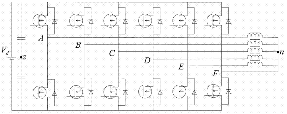
[0019] Specific implementation mode one: the following combination figure 1 and Figure 10 Describe this embodiment, the adjacent five-vector SVPWM method based on the five-phase six-wire topology described in this embodiment, in the five-phase six-wire topology, six bridge arms are formed by 12 power switch tubes, wherein: A phase, B phase The midpoints of the phase, C phase, D phase and E phase bridge arms are respectively connected to the input end of the motor, and the midpoint of the F phase bridge arm is directly connected to the neutral point n of the motor load.
[0020] The method includes the following steps:
[0021] Step 1. The 12 power switch tubes in the five-phase six-wire topology for SVPWM modulation have a total of 64 switching states, and calculate the voltage space vectors corresponding to the 64 switching states to obtain 64 voltage space vectors;
[0022] Step 2, judge the position of the reference voltage space vector, select five adjacent non-zero vol...
specific Embodiment approach 2
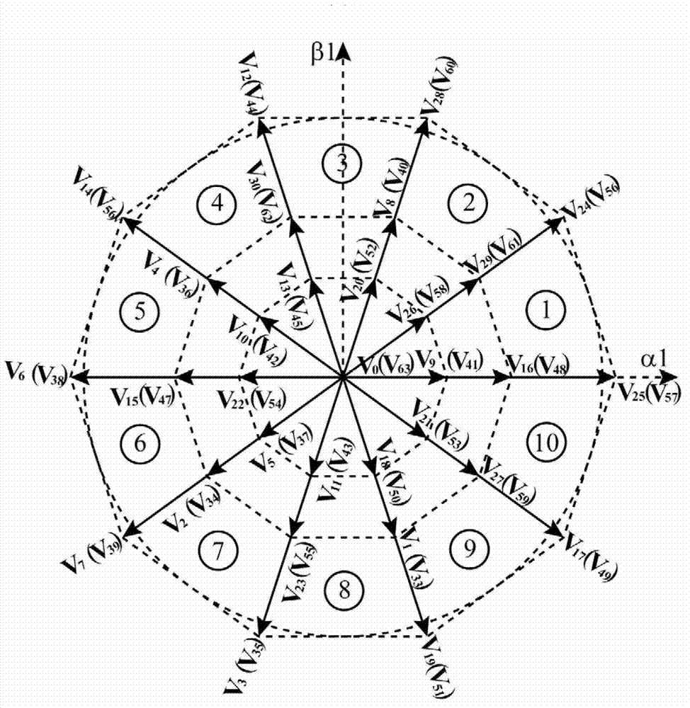
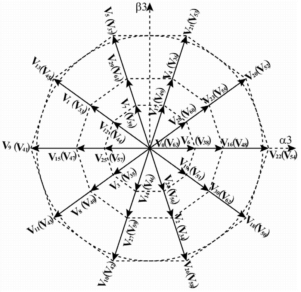
[0026] Specific implementation mode two: the following combination Figure 1 to Figure 3 Describe this embodiment, this embodiment will further explain Embodiment 1, and obtain 64 voltage space vectors V in step 1 k , k=0,1,2,..., the process of 63 is:
[0027] In the five-phase six-wire topology, six bridge arms are formed by 12 power switch tubes, and the switching function of each bridge arm is S i , i=A, B, C, D, E, F, the upper bridge arm of the i-th bridge arm is turned on, denote S i = 1, the lower bridge arm of the i-th bridge arm is turned on, denote S i = 0;
[0028] switch function press [S F , S A , S B , S C , S D , S E ] in order, with [S F , S A , S B , S C , S D , S E ] The binary code S composed of F S A S B S C S D S E The corresponding decimal value k represents the switch state, k=0, 1, 2,..., 63,
[0029] According to the formula
[0030] V k = ...
specific Embodiment approach 3
[0047] Specific implementation mode three: the following combination Figure 1 to Figure 7 Describe this embodiment, this embodiment will further explain Embodiment 1, 2 or 3, the position judgment of the reference voltage space vector and the selection process of the action vector in step 2 are as follows:
[0048] Denote the reference voltage space vector V refl = V α 1 r V β 1 r V z r ,
[0049] Step 21. According to the projection of the voltage space...
PUM
 Abstract
Description
Claims
Application Information
 - R&D Engineer
- R&D Manager
- IP Professional
- Industry Leading Data Capabilities
- Powerful AI technology
- Patent DNA Extraction
Browse by: Latest US Patents, China's latest patents, Technical Efficacy Thesaurus, Application Domain, Technology Topic, Popular Technical Reports.
© 2024 PatSnap. All rights reserved.Legal|Privacy policy|Modern Slavery Act Transparency Statement|Sitemap|About US| Contact US: help@patsnap.com


