Cyclonic separation apparatus

一种分离装置、旋风分离器的技术,应用在吸尘器、胶体化学、化学仪器和方法等方向,能够解决分离效率低分离效率等问题

Inactive Publication Date: 2013-04-17
BLACK & DECKER INC
View PDF12 Cites 63 Cited by
  • Summary
  • Abstract
  • Description
  • Claims
  • Application Information

AI Technical Summary

Problems solved by technology

The separation efficiency of the first cyclonic separation unit is lower than the separation efficiency of the second cyclonic separation unit

Method used


Image

  • Cyclonic separation apparatus
  • Cyclonic separation apparatus
  • Cyclonic separation apparatus

Examples


Embodiment Construction

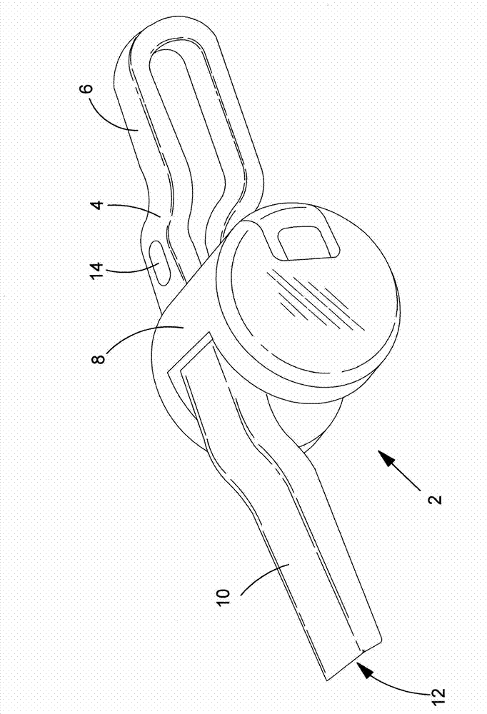
[0078] refer to figure 1 , which shows a first embodiment of a hand-held vacuum cleaner 2 comprising: a main body 4; a handle 6 connected to the main body 4; a cyclonic separation device 8 mounted on the main body and transversely across the main body; and a dirty air channel 10 having a dirty air inlet 12 at one end. The vacuum cleaner includes: an electric motor that engages a fan for generating air flow through the vacuum cleaner; and a rechargeable battery (not shown) Provides electrical energy to the motor when electrically connected to the motor.

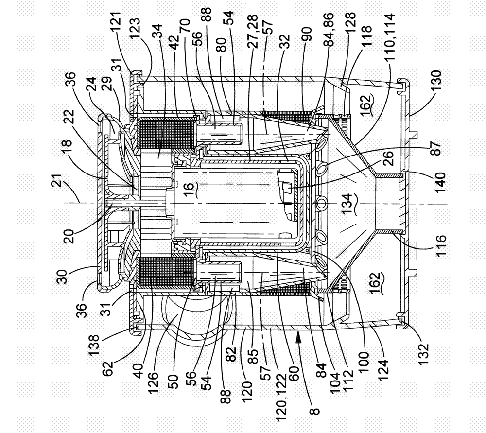
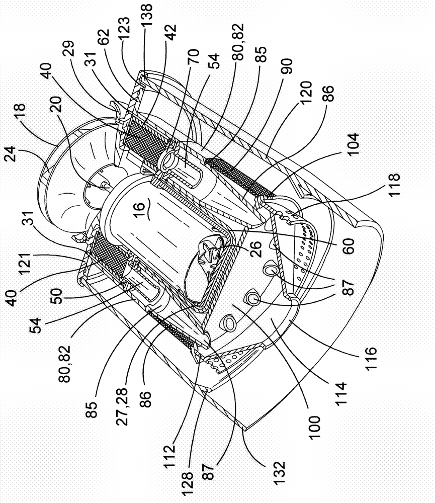
[0079] refer to Figure 2 to Figure 8 , which shows a structure including a motor 16, a fan 18 and a cyclonic separation device 8. The electric motor has a drive shaft 20 with a central axis 21 . The fan is a centrifugal fan 18 with an axial inlet 22 facing the motor and a tangential outlet 24 . The diameter of the fan is 68mm. The fan is mounted on the drive shaft that sits on top of the motor. In use, an electric moto...


PUM


Abstract

A cyclonic separation apparatus (208) for a vacuum cleaner (202), the cyclonic separation apparatus (208) comprising: a first cyclonic separating unit (360) comprising a hollow cylindrical dirt container (320) with a central axis (321) and an air inlet port (326) arranged tangentially through a side of the dirt container (320); a second cyclonic separating unit (350) comprising at least one cyclone (284) with an axial inlet port (288), an axial outlet port (256) and a discharge nozzle (287); a substantially cylindrical intermediate wall (290) surrounding the inlet port (288) of the at least one cyclone (284); and at least one protruding lip (304, 328) arranged to impede return of separated material from a longitudinal end of the dirt container (320), wherein the at least one lip (304, 328) protrudes radially inwardly from an inner surface of the dirt container (320) and / or radially outwardly from the intermediate wall (290).

Description

technical field [0001] The present invention relates to cyclonic separation devices. The invention relates particularly, but not exclusively, to cyclonic separation devices for use in vacuum cleaners. Background technique [0002] Vacuum cleaners are well known for collecting dust and dirt, but wet and dry variant vacuum cleaners capable of collecting liquids are also known. Typically vacuum cleaners are intended for use in residential environments, but they may also be used in other environments such as construction sites or gardens. Typically, they are powered by electricity and thus include: an electric motor; a fan connected to the output shaft of the motor; an inlet for dirty air; an outlet for clean air; and for dust, dirt (and possibly liquids) collection chamber. Power for the motor may be provided by mains power, in which case the vacuum cleaner will also include a power cord; by a removable and replaceable battery pack; or by one or more built-in rechargeable ba...

Claims


Application Information

Patent Timeline
Patent Type & Authority Applications(China)
IPC IPC(8): A47L9/16
CPCA47L9/1683A47L9/1641Y10S55/03A47L9/1608A47L5/24A47L9/1625A47L9/165A47L9/1666A47L9/2884A47L9/1633
Inventor 凯文·史密斯
Owner BLACK & DECKER INC
Why Eureka
Try Eureka