
Wheel assembly for motor vehicle

A wheel assembly and wheel technology, applied in the direction of wheels, wheel manufacturing, vehicle parts, etc., can solve problems such as high risk, deformation of rims, and difficulty in wheel replacement, and achieve the effects of simplifying maintenance operations, reducing weight, and avoiding warping

Inactive Publication Date: 2013-04-10
BAYERISCHE MOTOREN WERKE AG
View PDF8 Cites 10 Cited by
  • Summary
  • Abstract
  • Description
  • Claims
  • Application Information

AI Technical Summary

Problems solved by technology

If the brake disc, which is hugged on the inside, is fixed to such a conventional wheel rim with one-sided wheel guidance, the deformation of the rim due to the uneven tightening of the wheel bolts alone will exceed the permissible tolerance
[0007] Replacing a wheel with the brake disc fixed on the rim is significantly more difficult since the brake disc must be extracted or inserted from the brake caliper during disassembly or assembly
High risk of mishandling during assembly or actuating the brake, e.g. when the brake disc is removed

Method used


Image

  • Wheel assembly for motor vehicle
  • Wheel assembly for motor vehicle
  • Wheel assembly for motor vehicle

Examples


Embodiment Construction

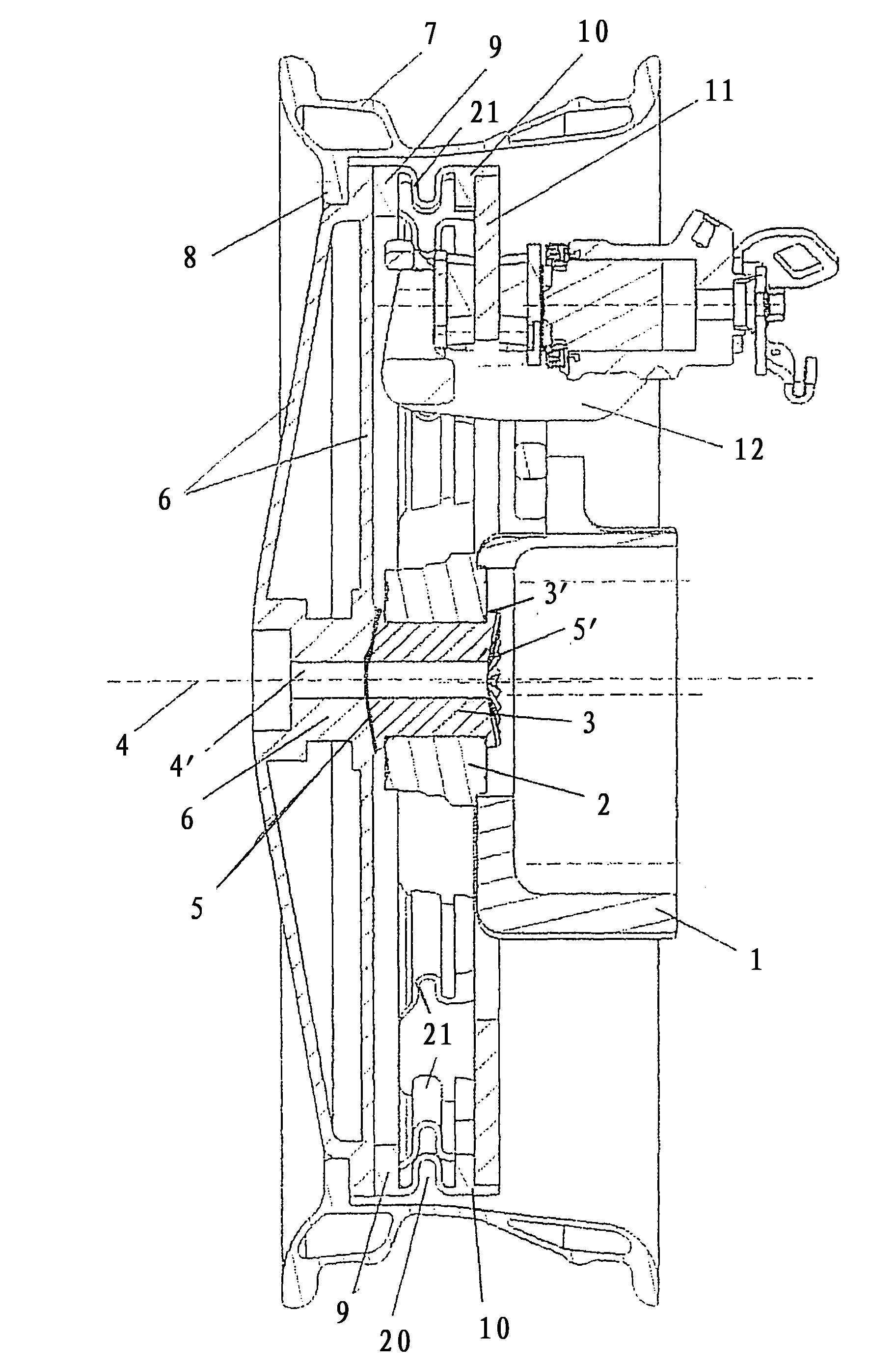
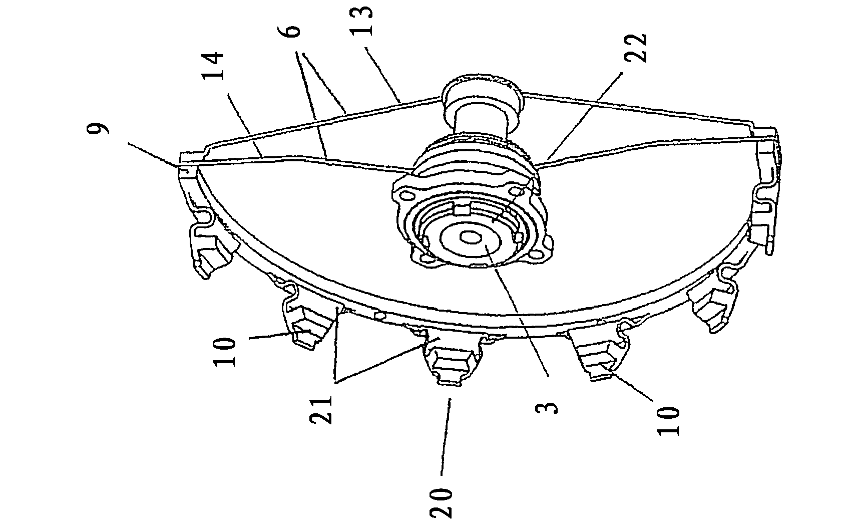
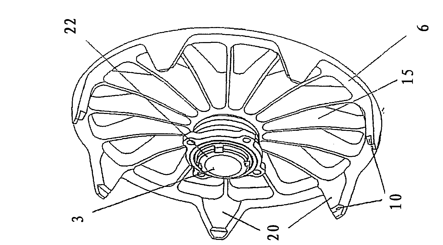
[0027] Wheel frame 1 is equipped with figure 1In the wheel assembly shown in , the wheel carrier fastens the outer ring of the wheel bearing 2 , which is only schematically shown. The inner ring of the wheel bearing 2 supports the hub 3 in a rotationally transmittable manner about an axis 4 drawn in dashed lines. The hub 3 is connected in a rotationally fixed and axially fixed manner to the wheel disk 6 via a flat-cut toothing 5 designed as a Voith face tooth. The wheel bearing 2 is fastened on the inner side of the wheel via its inner ring by means of the enlarged outer diameter 3' of the wheel hub 3 by means of flanges, wherein the enlarged outer diameter 3' is used to make the wheel hub 3 Another planar notched tooth groove 5' which is connected to the drive shaft not shown is made on the occasion. This is preferably done within the cutting process for the hub 3 by means of a cutting tool, not shown, preferably in one operation. The wheel hub 3 is thus connected on the w...


PUM


Abstract

The invention relates to a wheel assembly for mounting a motor vehicle wheel on one side, comprising a disk brake brake disk that is fixed to a wheel disk at the outer circumference of said wheel assembly, when seen in the radial direction, in the vicinity of a wheel rim, the brake caliper of said disk brake surrounding the brake disk over the brake disk inner circumference and being fixed to a wheel carrier that supports a stationary ring of a wheel bearing. The rotating ring of said wheel bearing supports a wheel hub that is connected to the wheel disk in a rotationally and axially fixed manner. The invention is characterized in that the connection of the wheel disk to the wheel hub is formed by a press fit or by a plane serration, in particular a Voith Hirth coupling.

Description

technical field [0001] The invention relates to a wheel assembly for a motor vehicle according to the preamble of the first claim. Background technique [0002] The construction of a conventional wheel and its support include the components of the wheel bearing, the hub with the wheel mounting flange and the rim with the tire. The rim is fastened to the wheel mounting flange with wheel bolts, wherein the brake disc is clamped between the rim and the wheel mounting flange. DE 101 32 429 A1 describes such a wheel bearing construction. The maximum friction radius of the brake disc is here determined by the dimensional chain: inner rim radius - height of the brake caliper bridge - half the lining height. Therefore, for powerful vehicles, it is often necessary to use larger rims to accommodate the necessary brake disc size. [0003] When dimensioning the brake disc, the largest possible friction radius should be aimed for, since this reduces the contact force of the brake cali...

Claims


Application Information

Patent Timeline
Patent Type & Authority Applications(China)
IPC IPC(8): B60B27/00F16D55/22F16D65/12
CPCB60B3/14B60B27/065B60B2310/316B60Y2200/10F16D65/12F16D2065/1372F16D2065/138B60B27/0031B60T1/065
Inventor R·施密特J·杜德科维亚克
Owner BAYERISCHE MOTOREN WERKE AG
Learn More