
Energy-utilizing water suction system

A vacuum device and water supply technology, which is applied in the configuration of water supply devices, water supply pools, construction, etc., can solve the problems of time-consuming, troublesome, large power consumption, etc., and achieve the effects of convenient operation, low cost, and energy saving

Inactive Publication Date: 2013-04-10
河南豪雨太阳能制品有限公司
View PDF5 Cites 2 Cited by
  • Summary
  • Abstract
  • Description
  • Claims
  • Application Information

AI Technical Summary

Problems solved by technology

[0002] There are few running water in the vast rural areas, and most of them rely on pressurized wells or machine wells to pump water for life or crop irrigation. Usually, corresponding pumping equipment and power supply lines are required, which consume a lot of electricity, especially for crop irrigation. Temporary structures are often erected Power supply lines are not only time-consuming and labor-intensive, but also pose serious safety hazards

Method used


Image

  • Energy-utilizing water suction system

Examples


Embodiment Construction

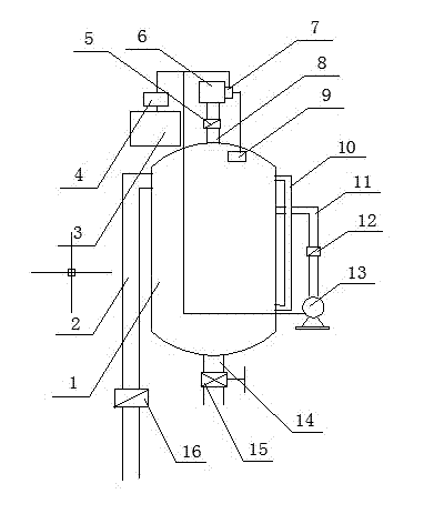
[0015] Such as figure 1 As shown, an energy drawing water device has a closed water storage tank 1, a drainpipe 14 is set at the lower part of the water storage tank 1, and a control valve 15 is set on the drainpipe 14. The upper part of the water storage tank 1 is connected with a water-drawing pipe 2, and the water-drawing pipe 2 should be sealed and connected with the water storage tank 1 without gas leakage, so as to ensure the negative pressure state of the upper cavity of the water storage tank 1. A one-way valve 16 can be arranged on the water drawing pipe 2 to avoid backflow of upper water. The side of the water storage tank 1 is provided with an observation and communication transparent tube 10, which can observe the water level in the water storage tank at any time, so as to replenish the water in time, ensure the water level in the water storage tank, and make it store the proper potential energy. . The top of described water storage tank 1 is provided with water ...


PUM


Abstract

The invention discloses an energy-utilizing water suction system, which is provided with a closed water storage tank, a water discharge pipe is arranged on the lower part of the water storage tank, the upper part of the water storage tank is connected with a water suction pipe, and a control valve is arranged on the water discharge pipe. Since the energy-utilizing water suction system adopts the closed water storage tank, when water is discharged by the water discharge pipe on the bottom of the water storage tank, the pressure difference energy between negative pressure generated in the upper part and the surface pressure is utilized to automatically suck well water or river water into the water storage tank, and thereby energy consumption is saved; the energy-utilizing water suction system can be used for sucking domestic water when tap water supply facilities do not exist, sucking motor-pumped well water or canal water to irrigate farmlands and lifting water from a diversion canal for irrigation. The energy-utilizing water suction system has a simple structure, is convenient to operate, not only can be fixed, but also can be mounted on a motor vehicle for mobile use, and can be used in any places without being limited by external conditions; and the fabrication cost is low.

Description

technical field [0001] The invention relates to the technical field of water drawing equipment, in particular to an energy drawing water drawing device. Background technique [0002] There are few running water in the vast rural areas, and most of them rely on pressurized wells or machine wells to pump water for life or crop irrigation. Usually, corresponding pumping equipment and power supply lines are required, which consume a lot of electricity, especially for crop irrigation. Temporary structures are often erected Power supply lines are not only time-consuming and labor-intensive, but also pose serious safety hazards. Contents of the invention [0003] The purpose of the present invention is to overcome the above-mentioned shortcomings of the prior art, and provide an energy-inducing water-drawing device that can automatically pump water, save energy, and is easy to use and safe. [0004] In order to achieve the above object, the technical solution adopted by the pres...

Claims


Application Information

Patent Timeline
Patent Type & Authority Applications(China)
IPC IPC(8): E03B11/00
Inventor 姬松勇包东锋
Owner 河南豪雨太阳能制品有限公司
Learn More