
Optical fiber routing indicator and method for manufacturing same

An optical fiber and routing technology, applied in the field of optical fiber routing marking and its manufacturing, can solve the problems of difficult application of urban fiber-to-the-home network, large thickness of glass substrate, complicated process, etc., and achieve easy storage and transportation, cost reduction, and process reduction. The effect of complexity

Inactive Publication Date: 2013-04-03
SUZHOU HENGZHI ELECTRONICS TECH CO LTD
View PDF5 Cites 0 Cited by
  • Summary
  • Abstract
  • Description
  • Claims
  • Application Information

AI Technical Summary

Problems solved by technology

The process is complicated and the cost is high, so it is difficult to apply to urban fiber-to-the-home networks
In addition, the thickness of the glass substrate is relatively large, which will cause transmission loss

Method used


Image

  • Optical fiber routing indicator and method for manufacturing same
  • Optical fiber routing indicator and method for manufacturing same
  • Optical fiber routing indicator and method for manufacturing same

Examples


Embodiment Construction

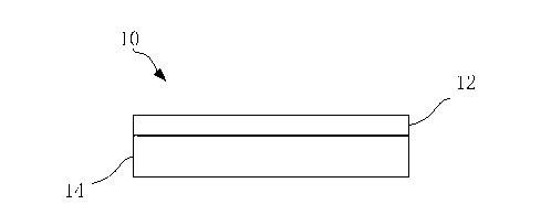
[0023] Such as Figure 4 As shown, the present invention provides an optical fiber routing marking device 10, which uses a flexible material as a substrate 14, and an optical film 12 is coated on it. The flexible material can transmit light, preferably polyimide. Wherein, the thickness of the substrate 14 is smaller than the wavelength of the signal in the optical fiber, thereby reducing the insertion loss. Preferably, the substrate 14 is less than 400 nanometers thick. Wherein, the optical film 12 only reflects the light emitted by the OTDR, but can transmit the service signal.

[0024] In an embodiment of the present invention, the service signal wavelengths may be 1270nm, 1310nm, 1550nm and 1650nm.

[0025] The wavelength of light emitted by OTDR is generally 1610nm, 1625nm or 1650nm.

[0026] Such as Figure 5 As shown, the present invention also provides a method 20 for manufacturing the optical fiber marking routing device, including coating an optical film on a lig...


PUM

PropertyMeasurementUnit
Wavelengthaaaaaaaaaa

Abstract

The invention discloses an optical fiber routing indicator which comprises a substrate and an optical film coated on the substrate. The substrate is made of light transmittance flexible materials, and the thickness of the substrate is smaller than wavelengths of signals in an optical fiber. The invention further discloses a method for manufacturing the optical fiber routing indicator and an optical fiber connector comprising the optical fiber routing indicator. According to the scheme, the optical fiber routing indicator, the method and the optical fiber connector have the advantages that the technological complexity can be reduced, and the optical fiber routing indicator is easy to cut, store and transport; the thickness of the substrate can be smaller than the wavelengths of the optical signals, so that loss is reduced; and complicated packaging measures are omitted.

Description

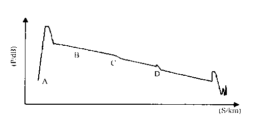
technical field [0001] The invention relates to the field of optical fiber network maintenance and testing, in particular to an optical fiber routing mark used for testing with an optical time domain reflectometer and a manufacturing method thereof. Background technique [0002] Optical Time Domain Reflectometry (OTDR) is the most important test method in optical cable engineering construction and optical cable line maintenance. The OTDR test is carried out by launching light pulses into the fiber and receiving the returned information at the OTDR port. When the light pulse is transmitted in the fiber, it will be scattered and reflected due to the nature of the fiber itself, connectors, joints, bending or other similar events. Part of the scattering and reflection will return to the OTDR, and the returned useful information is measured by the detector of the OTDR, and they are used as time or curve segments at different positions in the optical fiber. Based on the time it ...

Claims


Application Information

Patent Timeline
IPC IPC(8): H04B10/071G02B6/38
Inventor 王澎李瑾张徐亮林东缪爱俊
Owner SUZHOU HENGZHI ELECTRONICS TECH CO LTD
Learn More