
Exposure machine

A technology of exposure machine and light source device, which is applied in the field of exposure machine, can solve the problems of particle adhesion, easy generation of static electricity, etc., and achieve the effect of avoiding spots and improving exposure quality

Inactive Publication Date: 2013-04-03
BOE TECH GRP CO LTD +1
View PDF3 Cites 8 Cited by
  • Summary
  • Abstract
  • Description
  • Claims
  • Application Information

AI Technical Summary

Problems solved by technology

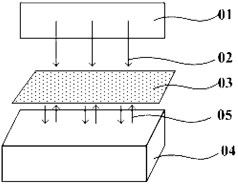
In addition, since the object to be exposed is in direct contact with the stage, many defects are prone to occur. In addition to the spots on the stage, particles are easy to adhere to the object to be exposed, and static electricity is easily generated by the contact and friction between the object to be exposed and the stage.

Method used


Image

  • Exposure machine
  • Exposure machine
  • Exposure machine

Examples


Embodiment Construction

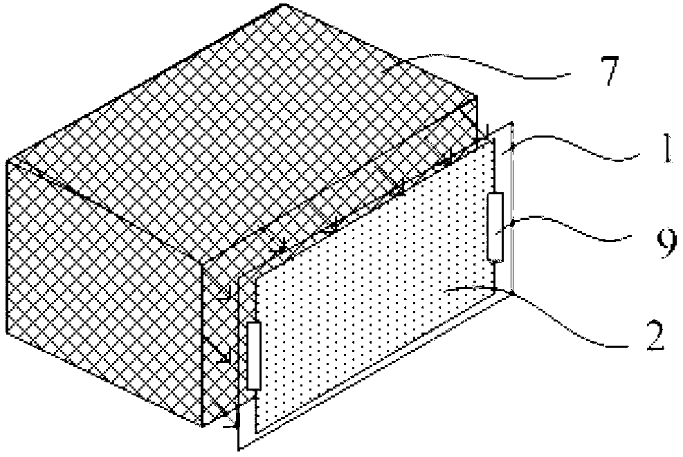
[0030] In order to avoid the spots on the stage generated during exposure, an embodiment of the present invention provides an exposure machine. In this technical solution, the object stage of the exposure machine adopts an object frame structure, and a fixing piece is arranged inside the object frame, and the object to be exposed is fixed in the object frame through the fixing piece, and the exposure light cannot be reflected after passing through the object to be exposed. Therefore, the stage spot on the object to be exposed is avoided, and the exposure quality is improved. In order to make the purpose, technical solution and advantages of the present invention clearer, the following specific examples are given to further describe the present invention in detail.

[0031] like image 3 As shown, the exposure machine of the embodiment of the present invention includes:

[0032] The loading frame 1, the inner side of the frame of the loading frame 1 is provided with a fixing ...


PUM


Abstract

The invention relates to the technical field of engineering exposure equipment, and discloses an exposure machine. The exposure machine comprises an object-carrying frame and a light source device, wherein a fixing element for fixing the exposed object is arranged at the inner side of the border of the object-carrying frame; and the light source device is located at one side of the plane on which the object-carrying frame is located, and the light-emitting direction is vertical to the plane on which the object-carrying frame is located. During exposure, the object-carrying frame cannot reflect the light ray which penetrates through the exposed object, thus avoiding the stops of an object-carrying stage. Additionally, the exposure machine adopts a vertical exposure mode, and can realize bidirectional exposure only by adding a triangular prism in the existing light source device, thus greatly increasing production efficiency.

Description

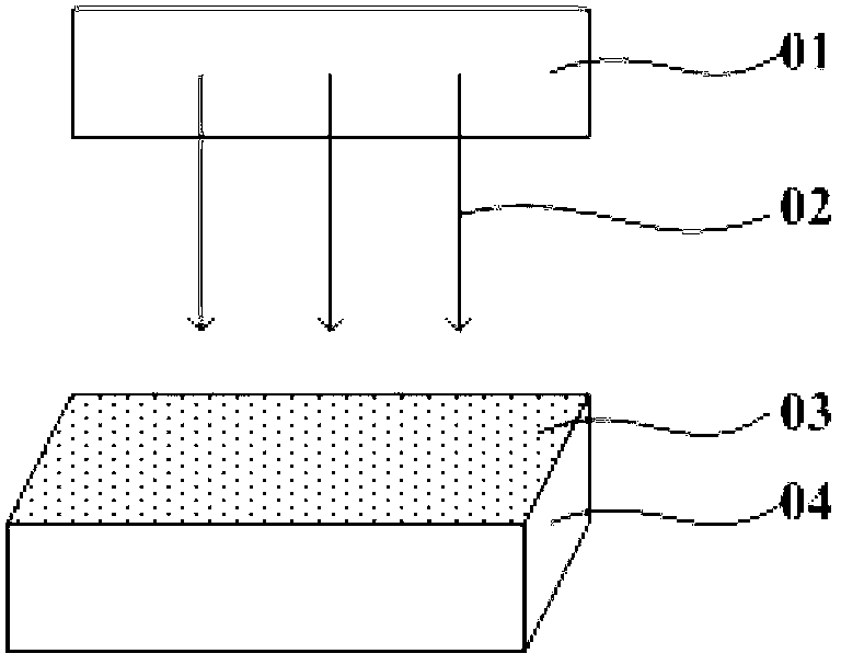
technical field [0001] The invention relates to the technical field of engineering exposure equipment, in particular to an exposure machine. Background technique [0002] With the wide application of organic films in the lithography process, the time required for exposure is getting longer and the exposure effect needs to be improved. Therefore, exposure has become the bottleneck of the entire lithography process, which seriously affects the engineering efficiency. [0003] Existing engineering exposure machines all adopt horizontal exposure methods, such as figure 1 As shown, the object 03 to be exposed is placed horizontally on the stage 04, and the light 02 is emitted from the light source device 01 to expose the object from top to bottom. [0004] The stage of this exposure machine is a solid structure, and the stage is in contact with the entire surface of the object to be exposed. The disadvantages of this exposure machine are, for example, figure 2 As shown, after ...

Claims


Application Information

Patent Timeline
Patent Type & Authority Applications(China)
IPC IPC(8): G03F7/20
CPCG03F7/70708G03F7/2008
Inventor 陆忠李炳天黄丽娟靳福江
Owner BOE TECH GRP CO LTD
Learn More