Eureka AIR delivers breakthrough ideas for toughest innovation challenges, trusted by R&D personnel around the world.

Ammonia circulation-based method and device for carbonating fixation of CO2 in coal-fired flue gas

A coal-fired flue gas and carbonation technology, which is applied in chemical instruments and methods, separation methods, air quality improvement, etc., can solve problems such as no better treatment or resource recovery methods

Inactive Publication Date: 2013-04-03
SOUTHEAST UNIV
View PDF7 Cites 15 Cited by
  • Summary
  • Abstract
  • Description
  • Claims
  • Application Information

AI Technical Summary

Problems solved by technology

[0004] Calcium carbide slag is the industrial waste produced by the hydrolysis of calcium carbide to produce acetylene in the production process of polyvinyl chloride; according to statistics, in 2011, my country's polyvinyl chloride production capacity reached 21.62 million tons, of which calcium carbide method accounted for about 80%, and the amount of calcium carbide slag produced It has reached more than 20 million tons and maintained a high-speed growth trend. At present, there is no better treatment or resource recovery method

Method used


Image

  • Ammonia circulation-based method and device for carbonating fixation of CO2 in coal-fired flue gas
  • Ammonia circulation-based method and device for carbonating fixation of CO2 in coal-fired flue gas

Examples


Embodiment 1

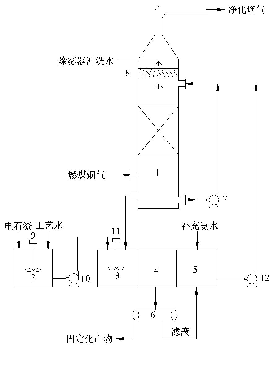
[0046] Contains CO 2 Coal-fired flue gas is produced by a fully automatic coal-fired boiler with a gas volume of 10Nm 3 / h; after dedusting and wet desulfurization, CO in the flue gas 2 The concentration is 13% (V / V), the flue gas temperature is 50°C, it enters a packed absorption tower with a diameter of 100mm, and the ammonia solution with a mass concentration of 10% is used as CO 2 Absorption liquid, gas-liquid countercurrent contact in the absorption tower, the contact time is 5s, the temperature of the ammonia absorption liquid is 40°C, the absorption pressure is normal pressure, and the liquid-gas ratio is 5L / Nm 3 ; On-line test by gas chromatograph, CO 2 The removal rate is 76%; the removal of CO 2 The final purified flue gas leaves the packed absorption tower from the top of the tower after demisting and washing with clean water. Ammonia absorbs CO 2 The generated rich solution containing ammonium bicarbonate and ammonium carbonate components and calcium carbide s...

Embodiment 2

[0048] Ammonia absorbs CO 2 After the slurry obtained by the carbonation reaction between the generated rich liquid and the calcium carbide slag slurry is filtered, the filtrate is directly used as CO without adding ammonia water. 2 Absorption liquid, all the other are the same as embodiment 1; After testing, ammoniacal liquor mass concentration is 8% in the filtrate, CO 2 The removal rate was 62%; the filter residue was dried by thermogravimetric analyzer and XRD test, CaCO 3 Accounted for 83%.


PUM


Abstract

The invention discloses an ammonia circulation-based method and device for carbonating fixation of CO2 in coal-fired flue gas. The method comprises the following steps that ammonia water is sprayed for absorbing CO2 in the coal-fired flue gas, part of absorption liquid generated in reaction is recycled for use, the rest of the absorption liquid flows into a regeneration pool through tower bottom so as to be reacted with added carbide slag slurry to be converted into calcium carbonate and ammonia water, after sediment through a sedimentation basin, supernatant liquor which is rich in ammonia flows into an absorption liquid mixed pool, and then a proper amount of ammonia water is added into the absorption liquid mixed pool so as to be sent to a CO2 absorption tower through a pump for reuse, after filtration of calcium carbonate sediment in the sediment pool, calcium carbonate is recycled, and the filtrate is sent to the absorption liquid mixed pool for reuse. According to the method, CO2 in the coal-fired flue gas is directly converted into calcium carbonate under normal temperature and pressure by taking ammonia water as an absorbent and taking carbide slag as a regenerant. Compared with the technology that CO2 of high concentration is obtained by ordinary ammonia water absorption and regeneration and carbonation seal is performed, the method has obvious technical economy advantages.

Description

1. Technical field [0001] The invention relates to CO in coal-fired flue gas 2 The technical field of capture and storage, specifically relates to a carbonation fixation of CO in coal-fired flue gas with ammonia water as absorbent and calcium carbide slag as regenerant 2 methods and devices. 2. Background technology [0002] The greenhouse gas CO produced by the burning of fossil fuels such as coal 2 The capture and storage of carbon dioxide has attracted widespread attention from the international community; among them, mineral carbonation imitation of the weathering process of natural calcium-magnesium silicate minerals is the key to achieve large-scale storage of CO 2 Important pathway for CO fixation by mineral carbonation compared to other storage technologies 2 The environmental risk is small, and CO can be achieved 2 permanent storage. CO 2 The main raw materials for mineral carbonation and fixation are wollastonite CaSiO 3 , olivine Mg 2 SiO 4 , Serpentine M...

Claims


Application Information

Patent Timeline
IPC IPC(8): B01D53/79B01D53/62B01D53/96
CPCY02A50/20
Inventor 杨林军潘丹萍熊桂龙
Owner SOUTHEAST UNIV
Why Eureka
Eureka Blog
Learn More