
Intraocular lens

A technology of intraocular lens and optical body, applied in the direction of intraocular lens, eye implant, etc., can solve problems such as increased risk, pigment loss, and difficulty in predicting long-term effects, and achieves minimization of mechanical stimulation, convenient processing and manufacturing, The effect of avoiding movement that obstructs or interferes with the pupil

Inactive Publication Date: 2013-04-03
王清扬
View PDF12 Cites 6 Cited by
  • Summary
  • Abstract
  • Description
  • Claims
  • Application Information

AI Technical Summary

Problems solved by technology

This method still has disadvantages. First, this method will increase the trauma caused by the operation, and it is difficult to predict the long-term impact of this trauma
In addition, since the surface of the iris contains more pigment, punching holes can easily cause the pigment to fall off
The effects of pigment loss may lead to an increased risk of secondary ocular hypertension, glaucoma, etc.
In addition, by turning up the upper eyelid, the hole left by the incision on the iris can be observed from the outside of the eye, which will also affect the appearance of the eye to a certain extent.

Method used


Image

  • Intraocular lens
  • Intraocular lens
  • Intraocular lens

Examples


Embodiment

[0072] Next, structural improvements of the intraocular lens according to the present invention will be specifically described with reference to examples.

no. 1 example

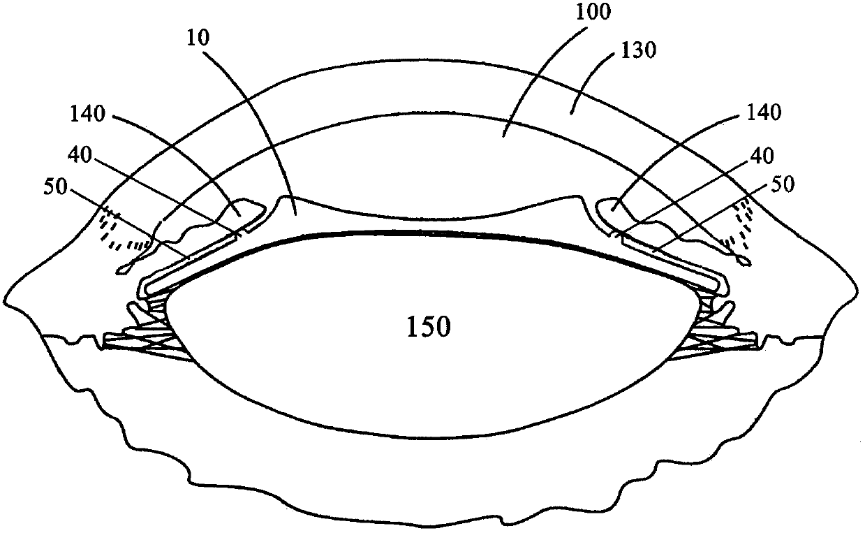
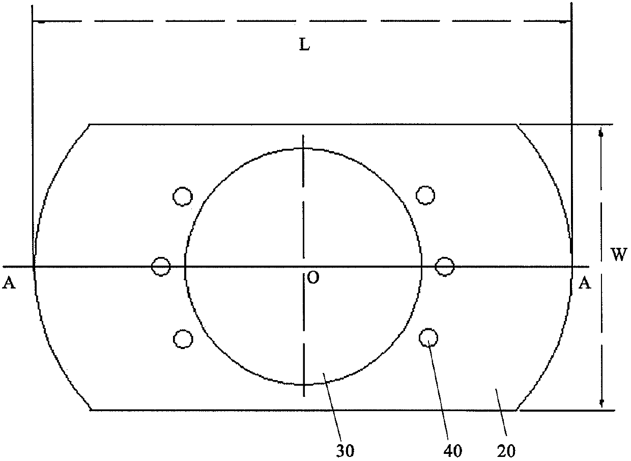
[0074] Please see attached Figure 1-3 , the illustrated embodiment is a phakic intraocular lens implanted in the posterior chamber of the eye. figure 1 It is a schematic cross-sectional view showing the position where the phakic intraocular lens is implanted in the posterior chamber of the eye according to the first embodiment of the present invention; figure 2 It is a schematic top view of the intraocular lens of this embodiment; image 3 is along figure 2 A schematic cross-sectional view of the intraocular lens of this embodiment taken along line A-A.

[0075] like 2 and image 3 As shown, the intraocular lens 10 includes an optical body 30 arranged in the middle, and a supporting body 20 is arranged around the optical body 30 for supporting the optical body 30 . In the present embodiment the optical body 30 is circular with a diameter of about 5 mm and its center is indicated by O. The total width W of the support body 20 is about 6mm, and the total length L is abou...

Embodiment 1

[0078] Embodiment 1 uses a soft material, PC-PRL (Phakic Posterior Chamber Refractive Lens) material produced by Hangzhou Baikang Medical Technology Co., Ltd. The specific gravity of this material is consistent with the specific gravity of aqueous humor, and the intraocular lens made can be suspended and centered in the eye, that is, it has "0" weight and "0" mechanical friction in the eye, so that it can maintain its position without relying on support. Intraocular stability.


PUM


Abstract

The invention discloses an intraocular lens which comprises an optical body and a support. Each of the optical body and the support is provided with a front surface and a rear surface. The front surface of the intraocular lens is provided with a plurality of protrusions on the part of the support, close to the edge of the optical body. After the intraocular lens is positioned in a posterior chamber, the protrusions contact with the iris. At least at the position around the protrusions, additional gaps are formed between the front surface of the intraocular lens and the iris and form additional channels for aqueous humor, and the aqueous humor in the posterior chamber is driven to flow into the pupil from the additional channels by bypassing the intraocular lens and enter the anterior chamber.

Description

technical field [0001] The present invention relates to an intraocular lens (IOL). More specifically, the present invention relates to an intraocular lens that can be implanted in the eye, coexists with the natural lens of the eye, and can be used to correct refractive errors of the eye. Background technique [0002] The applicant submitted an invention patent titled "Intraocular Refractive Lens and Its Implantation Method" on February 21, 2003, the application number is 03115498.0, and the publication number is CN1466934A, which is hereby cited in its entirety in a non-limiting manner. Incorporate this application, to facilitate understanding of the present invention. [0003] In recent years, with the improvement of ophthalmic microsurgery techniques and the popularization and improvement of intraocular lens (intraocular lens) implantation, the use of posterior chamber intraocular lens implantation not only makes it easier to maintain an appropriate physiological position...

Claims


Application Information

Patent Timeline
Patent Type & Authority Applications(China)
IPC IPC(8): A61F2/16
CPCA61F2/16A61F2002/161A61F2/1601A61F2/161A61F2002/1681
Inventor 王清扬齐备
Owner 王清扬
Learn More