
Wireless remote monitoring system and wireless remote monitoring method for reactive compensation device

A remote monitoring system and compensation device technology, applied in reactive power compensation, reactive power adjustment/elimination/compensation, circuit devices, etc., can solve the problems of difficult transplantation and modification, simple functions, unsightly user interface, etc., to achieve Wireless remote monitoring to realize the effect of local monitoring

Inactive Publication Date: 2013-03-27
ZHUZHOU NAT ENG RES CENT OF CONVERTERS
View PDF7 Cites 11 Cited by
  • Summary
  • Abstract
  • Description
  • Claims
  • Application Information

AI Technical Summary

Problems solved by technology

[0009] In the past, the monitoring system and it were usually developed by text language programming for a specific application object, the user interface was not beautiful, the development cycle was long, and it was difficult to transplant and change
In addition, the functions of the existing monitoring system are relatively simple. Generally, on-site monitoring is used. There is a man-machine interface on the equipment, and the operation information of the equipment is displayed on the man-machine interface. For remote substations, coal mines, metallurgy, etc. very inconvenient place

Method used


Image

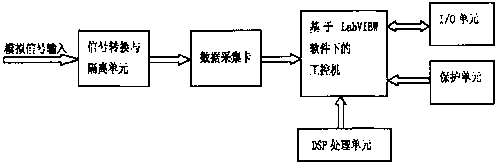
  • Wireless remote monitoring system and wireless remote monitoring method for reactive compensation device
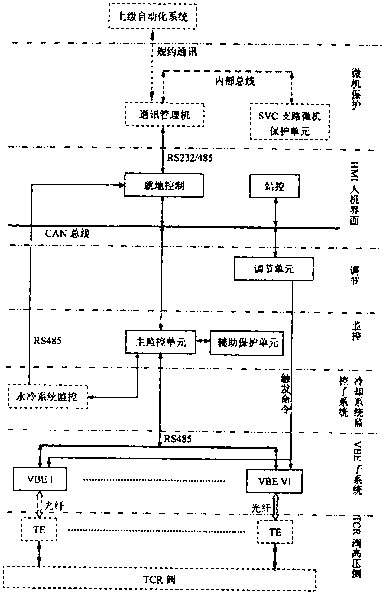
  • Wireless remote monitoring system and wireless remote monitoring method for reactive compensation device
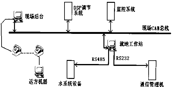
  • Wireless remote monitoring system and wireless remote monitoring method for reactive compensation device

Examples


specific Embodiment approach

[0079] A specific embodiment of a wireless remote monitoring method for a reactive power compensation device, comprising the following steps:

[0080] S100: the microcontroller 1 collects information data on the monitoring node of the reactive power compensation device 4, and sends the collected data to the CAN bus transceiver 2 through the eCAN controller 10;

[0081] S101: the wireless transceiver module 3 sends the data from the CAN bus transceiver 2 to the server 7 through GPRS and the Internet network;

[0082] S102: establish a database on the server 7, store and manage data of different nodes, and obtain power quality information and reports of the power grid through the database, so as to grasp the operating status of the reactive power compensation device and the entire power grid;

[0083] S103: The control information generated by the server 7 is sent to the wireless transceiver module 3 through GPRS and the Internet network, and then passes through the CAN bus tran...


PUM


Abstract

The invention discloses a wireless remote monitoring system and a wireless remote monitoring method for a reactive compensation device. The system comprises a CAN (controller area network) bus communication circuit and a wireless transceiving module which form a monitoring node of the wireless remote monitoring system. The CAN bus communication circuit comprises a microcontroller and a CAN bus transceiver. The microcontroller acquires data on reactive compensation device nodes and transmits the acquired data to the CAN bus transceiver through an eCAN controller, the wireless transceiving module transmits the data to a sever through GPRS (general packet radio service) and Internet, a database is built at the server for storing and managing data of different nodes, and the sever transmits a actuating signal to the reactive compensation device along the same path through power grid power quality information acquired by the server. The wireless remote monitoring system and the wireless remote monitoring method guarantees data acquisition, data processing, data calculation and data safety, satisfies local monitoring of the reactive compensation device, and realizes remote monitoring.

Description

technical field [0001] The invention relates to an electric power monitoring system and its method, in particular to a wireless remote monitoring system and its method suitable for an automatic reactive power compensation device. Background technique [0002] The reactive power compensation device is the main equipment in the substation and the power industry. It is mainly used to compensate the reactive power of the power system, improve the power reputation of the system, improve the quality of power supply, reduce the reactive power loss of the line, and improve the power transmission capacity of the grid. There are mainly SVC (thyristor switched reactor), SVG (static var generator), TSC (thyristor switched capacitor), and FC. It is mainly used in reactive power compensation and harmonic control in steel, chemical, smelting, and power grid industries. With the continuous increase of high-power nonlinear and impact loads, the application of high-voltage reactive power com...

Claims


Application Information

Patent Timeline
Patent Type & Authority Applications(China)
IPC IPC(8): H02J3/18H02J13/00
CPCY04S10/22Y02E60/7838Y04S40/126Y02E40/30Y04S40/124Y04S40/127Y02E60/7861Y02E60/7869Y04S40/128Y02E60/7853Y02E40/74Y02E40/70Y02E60/00
Inventor 曹洋李保国谭胜武黄燕艳梁文超何伟刘永丽唐建宇彭勃杨磊
Owner ZHUZHOU NAT ENG RES CENT OF CONVERTERS
Learn More